background image

SV-CLCD56B/70B Quick Installation Guide 

March 2007 


SV-CLCD56B_70B QIG Ver.1.0.doc


SV-625B Camera 

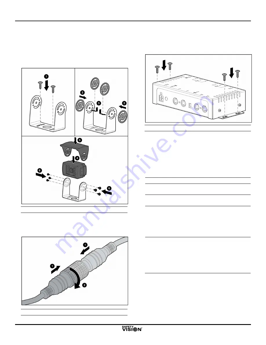
1.  Select an appropriate mounting location for the 

camera, which should be mounted on a solid, flat 
surface at the highest possible point on the vehicle. 

2.  With the provided hardware, affix the camera 

mounting bracket to the mounting surface, and secure 
the camera and sun visor in the bracket. 


 Installing the Camera 

3.  Connect the male connector of the camera pigtail  to 

the female connector of the provided 65-foot extension 
cable. Align the arrows on both cable connectors, and 
then hand-tighten, as follows: 


 Connecting the Camera Pigtail to the Extension Cable 


SV-CBB-56-70 Control Box 

1.  Select a discreet location for the control box, such as 

under the vehicle dashboard. Use the provided screws 
to secure the control box to the mounting surface. 


 Installing the Control Box 

2.  Route the camera extension cable to the control box 

and insert the connector in the 

CAM1

 receptacle. 

3.  Route the monitor cable to the control box and insert 

the connector in the 

MONITOR

 receptacle 

4.  Route the control box system power cable from the 

control box to the vehicle battery, and connect the 
unterminated wires as follows: 


Wire Color 

Vehicle Location 

Red 

Vehicle wire that has 12 VDC when 
the vehicle ignition is on 

Black 
(Ground) 

Vehicle chassis 

Green  
(Trigger 1) 

Vehicle wire that has 12 VDC when 
the vehicle transmission is in reverse 
gear (typically the wire for the backup 
lights). (When this wire has 12 VDC, 
the monitor receives input from 
Camera 1.) 

White  
(Trigger 2) 
(Optional) 

Vehicle wire that has 12 VDC when a 
separate event (such as activating a 
turn signal) occurs. (When this wire 
has 12 VDC, the monitor receives 
input from an optional Camera 2. 
Camera 1 input takes priority over 
Camera 2 input.) 

5.  Insert the 4-pin Molex connector of the system power 

cable into the 

POWER IN

 receptacle on the rear panel 

of the control box. 

Содержание SV-CLCD56B

Страница 1: ...driver to both see and hear activity within the camera s range Although two cameras can be connected to the SV CLCD56B 70B system only one camera is provided with the system Components of the SV CLCD56B 70B system include Safety Vision SV LCD56B or SV LCD70B Monitor which features Either a 5 6 inch or 7 0 inch TFT LCD screen Wide field of view Integrated speaker Safety Vision SV 625B KIT which inc...

Страница 2: ... senses available light and adjusts monitor brightness accordingly C MENU BUTTON initiates display of onscreen user controls for image contrast and brightness and speaker volume D BUTTON UP button increases the value for Setup menu items such as Volume E BUTTON DOWN button decreases the value for Setup menu items such as Volume F POWER CAM SELECT BUTTON when pressed and held for 1 second turns the...

Страница 3: ...rrel type connector of an optional power cable not typically used in SV CLCD56B 70B system installations K POWER IN accepts the 4 pin Molex connector of the control box system power cable Optional Components Optional components for the SV CLCD56B 70B system include a remote control device Part Number SV LCDB CP for the monitor In addition devices other than the components supplied with the SV CLCD...

Страница 4: ...ng the Control Box 2 Route the camera extension cable to the control box and insert the connector in the CAM1 receptacle 3 Route the monitor cable to the control box and insert the connector in the MONITOR receptacle 4 Route the control box system power cable from the control box to the vehicle battery and connect the unterminated wires as follows Wire Color Vehicle Location Red Vehicle wire that ...

Страница 5: ...h 4 3 7 0 inch 16 9 Response Time 30 ms at 25 C View Angle CR 10 40 65 65 65 up down left right Field of View 135 diagonal 108 horizontal Brightness 500 cd m2 Contrast Ratio 300 1 Automatic Brightness Control Light sensor Day Night switch On Screen Display Controls Brightness Contrast Volume Color Languages Operating Temperature 5 F to 149 F 15 C to 65 C Storage Temperature 13 F to 185 F 25 C to 8...

Страница 6: ...caused by misuse accident improper installation improper maintenance or use in violation of instructions furnished with the product to units that have been altered or modified without authorization of SV to damage to products or parts thereof that have had the serial number removed altered defaced or rendered illegible or to any failure of the product to function caused by burglary fire flood war ...

Отзывы: