

DIMENSIONS:
Dimensions: 3.684 x 2.002 x 0.775”, (93.57 x 52.88 x 19.68 mm)
Weight: 2.4 oz. (68.03g)
ENVIRONMENTAL SPECIFICATIONS:
Temperature -30º to +75º C (operating); -40º to +85º C (storage)
Humidity 95%RH @ 50º C non-condensing
Shock and Vibration U.S. Military Standards 202G and 810F, SAE J1455
Getting Started
Kit Contents:
•
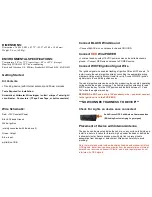
Tracking device (with internal antenna) and Power Harness
Tools Required for Installation:
Screwdriver, Voltmeter, Wire stripper / cutter / crimper. Tester light/
circuit tester. Connectors: (T-Taps, Fuse Taps, or butt connectors)
Connect BLACK Wire/Ground
•
Connect BLACK wire on harness to chassis GROUND.
Connect
RED
Wire/POWER
•
Locate a fused, constant 12 VDC power source and a suitable chassis
ground.
•
Connect RED wire on harness to POWER source.
Connect WHITE Ignition Signal Wire
The ignition signal wire enables tracking of ignition ON and OFF events. To
install, locate the vehicle ignition wire by consulting the appropriate wiring
diagrams. Using a test light/circuit tester to verify, Connect WHITE ignition
signal wire to the vehicle’s ignition source.
The vehicle ignition wire can be verified by measuring the vehicle’s operating
voltage while the engine is running. The vehicle’s ignition wire should read
0VDC when the key is in the OFF position and typically between 11V and
14V when the engine is running.
BEWARE! Do NOT source to a 12V accessory wire – you must connect
to the ignition wire in the FUSE BOX.
***NOW CONNECT HARNESS TO DEVICE***
Check For Lights on device once connected:
Solid Green=GPS Solid Amber=Communication
(If Blinking Device is trying to get signal)
Placement of Device with Internal Antenna
The device can be mounted inside the vehicle, on any surface, label side up.
Install in a secure location far forward, high up under the dash or behind the
instrument cluster. Secure excess wire with zip ties to prevent cable
assemblies from damage or detachment. Wrap wires carefully to avoid
pinching!
Note that metal and metal oxide windshields (lead-based window tint) block
GPS signals. Install device above or away from these materials so internal
antenna can receive and transmit. Plastic, wood, and regular glass do not
interfere with GPS signals.
Wire Schematic:
Red: +12V Constant Power
Black: Chassis Ground
White: Ignition
(mainly concerned with the above 3)
Green: Output
Blue: input
white/blue: 1BB