background image

NXP Semiconductors

UM11637

FRDMGD3160DCMHB evaluation board

6 Installation and use of software tools

Software for FRDMGD3160DCMHB is distributed with the FlexGUI tool (available on

NXP.com). Necessary firmware comes pre-installed on the FRDM-KL25Z with the kit.
Even if the user intends to test with other software or PWM, it is recommended to install

this software as a backup or to help debugging.

6.1 Installing FlexGUI on your computer

The latest version of FlexGUI supports the GD3100 and GD3160. It is designed to run on

any Windows 10 or Windows 8 based operating system. To install the software, do the

following:

1. Go to 

www.nxp.com/FlexGUI 

 and click 

Download

.

2. When the FlexGUI software page appears, click 

Download

 and select the version

associated with your PC operating system.

3. FlexGUI wizard creates a shortcut, an NXP FlexGUI icon appears on the desktop. By

default, the FlexGUI executable file is installed at 

C:\flexgui-app-des-gd31xx.exe

.

Installing the device drivers overwrites any previous FlexGUI installation and replaces

it with a current version containing the GD31xx drivers. However, configuration files

(.spi) from the previous version remain intact.

6.2 Configuring the FRDM-KL25Z microcode

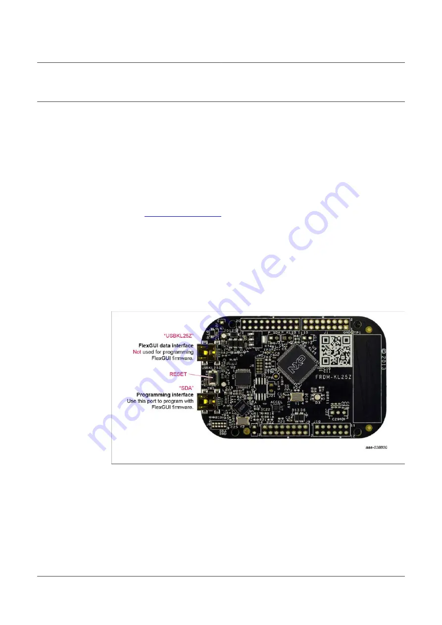
Figure 15. FRDM-KL25Z setup and interface

By default, the FRDM-KL25Z delivered with this kit is preprogrammed with the current

and most up-to-date firmware available for the kit.
A way to check quickly that the microcode is programmed and the board is functioning

properly, is to plug the KL25Z into the computer, open FlexGUI, and verify that the

software version at the bottom is 6.4 or later.
If a loss of functionality following a board reset, reprogramming, or a corrupted data

issue, the microcode may be rewritten per the following steps:

UM11637

All information provided in this document is subject to legal disclaimers.

© NXP B.V. 2022. All rights reserved.

User guide

Rev. 2 — 3 February 2022

23 / 42

Содержание FRDMGD3160DCMHB

Страница 1: ...22 User guide Document information Information Content Keywords GD3160 DCM 1000X SiC high voltage gate driver SiC power module Abstract This document describes the operation of the FRDMGD3160DCMHB evaluation board compatible with the DCM 1000X SiC evaluation kit ...

Страница 2: ...iption 2 20220203 release version Modifications Update with latest board images 1 20210921 initial version Revision history UM11637 All information provided in this document is subject to legal disclaimers NXP B V 2022 All rights reserved User guide Rev 2 3 February 2022 2 42 ...

Страница 3: ...pends on proper printed circuit board layout and heat sinking design as well as attention to supply filtering transient suppression and I O signal quality The product provided may not be complete in terms of required design marketing and or manufacturing related protective considerations including product safety measures typically found in the end device incorporating the product Due to the open c...

Страница 4: ... title 4 After reviewing the Overview tab visit the other product related tabs for additional information Documentation download current documentation Software Tools download current hardware and software tools Buy Parametrics purchase the product and view the product parametrics After downloading files review each file including the user guide which includes setup instructions If applicable the b...

Страница 5: ...s on the GD3160 gate drive devices in either daisy chain or standalone configuration The KITGD316xTREVB translator board is used to translate 3 3 V signals to 5 0 V signals between the MCU and GD3160 gate drivers The evaluation kit can be connected to a compatible SiC module for half bridge or three phase evaluations and applications development 4 2 Board features Capability to connect to DCM 1000...

Страница 6: ...Compatible with negative gate supply Compatible with 200 V to 1700 V IGBTs power range 125 kW Table 1 Device features 4 4 Board description The FRDMGD3160DCMHB is a half bridge or three phase evaluation board populated with two GD3160 single channel IGBT or SiC gate drive devices The board supports connection to an FRDM KL25Z microcontroller for SPI communication configuration programming and moni...

Страница 7: ... 12 V VSUP domain that interfaces with the MCU and GD3160 control registers through the 24 pin connector interface Low side driver and high side driver domains are driver control interfaces to DCM 1000X module single phase connections and test points UM11637 All information provided in this document is subject to legal disclaimers NXP B V 2022 All rights reserved User guide Rev 2 3 February 2022 7...

Страница 8: ...input low side 6 INTBL interrupt bar low side 7 MOSI master out slave in low side or both sides 8 SCLK serial clock input 9 MISOL master in slave out low side 10 EN_PS MCU control of flyback power supply 11 FSSTATEL fail safe state low side 12 GND ground 13 FSENB fail safe enable high side and low side 14 MISO master in slave out high side or both sides Table 2 Low voltage domain 24 pin connector ...

Страница 9: ...cle encoded signal high side 21 PWMH PWM input high side 22 FSSTATEH fail safe state high side 23 GND ground 24 INTBH interrupt bar high side Table 2 Low voltage domain 24 pin connector definitions continued 4 4 2 Test point definitions All test points are clearly marked on the evaluation board Figure 4 shows the location of various test points Figure 4 Key test point locations UM11637 All informa...

Страница 10: ...omain FSISOL high voltage domain fail safe low side test point DESATL VCE desaturation test point connected to low side driver DESAT pin and circuitry VCCREGL VCC regulator low side test point VEEL negative voltage supply test point for low side driver gate VDCLINK DC link voltage test point at voltage divider Vds LS collector test point connection terminal on low side High side driver domain VCCH...

Страница 11: ...short circuit testing open default VCCREG controls gate voltage JVCCH J2 and JVCCL J8 closed VCC and VCCREG are tied together 1 2 default chip select for normal operation CSB J23 2 3 chip select for daisy chain operation closed default normal operation MOSI J22 open daisy chain operation 1 2 default normal operation MISO J24 2 3 daisy chain operation closed default normal operation MISO J21 open d...

Страница 12: ...upply enable PS_EN J1 2 3 default flyback supply enable tied to VSUP Table 4 Jumper definitions continued 4 4 4 Bottom view Figure 6 Evaluation board bottom view UM11637 All information provided in this document is subject to legal disclaimers NXP B V 2022 All rights reserved User guide Rev 2 3 February 2022 12 42 ...

Страница 13: ...e gate that controls the turn off current for SiC MOSFET gate RAMC series resistor between SiC gate and AMC input pin of the GD3160 driver for gate sensing and active Miller clamping Figure 7 Gate drive resistors The selected gate resistors are default values compatible with DCM 1000X module It remains the responsibility of the user always to verify the operation within the safe operating area SOA...

Страница 14: ...dom KL25Z is an ultra low cost development platform for Kinetis L series MCU built on Arm Cortex M0 processor Figure 8 Freedom development platform UM11637 All information provided in this document is subject to legal disclaimers NXP B V 2022 All rights reserved User guide Rev 2 3 February 2022 14 42 ...

Страница 15: ...for 3 3 V compatible gate drive 1 2 default selects PWM high side control from KL25Z MCU PWMH_SEL J4 2 3 leaves PWM high side open for control from external input FRDMGD3160DCMHB J13 1 2 default selects PWM low side control from KL25Z MCU PWML_SEL J5 2 3 leaves PWM low side open for control from external input FRDMGD3160DCMHB J13 Table 5 Translator board jumper definitions UM11637 All information ...

Страница 16: ...capacitor as shown in Figure 10 Double pulse and short circuit testing can be conducted utilizing Windows based PC with FlexGUI software Danfoss is a trademark of Danfoss A S Figure 10 Half bridge setup Suggested equipment needed for test DCM 1000X module and compatible DC link capacitor from Danfoss Silicon Power 1 FRDMGD3160DCMHB 1 KITGD316xTREVB and 1 FRDM KL25Z Rogowski coil high current probe...

Страница 17: ...L25Z microcontroller is shipped with proper firmware already flashed See Section 6 for additional details 6 Supply 12 V DC power to the low voltage domain of the evaluation board by using VSUP TP6 and GND TP7 7 Start FlexGUI communications and check VCCL VCCH VEEL VEEH voltage levels regarding GNDH and GNDL test points If VCC voltages are low adjust R65 potentiometer 8 PWM double pulse and short c...

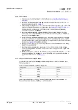
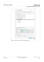
Страница 18: ...ng jumpers Designator Signal Position J21 MISO closed J22 MOSI open J23 CSB 2 3 J24 MISO 2 3 Table 7 Daisy chain SPI jumpers configuration Select the appropriate FlexGUI kit GD3160 Half Bridge EVBs and check that the Feature Set under Advanced Settings is set to daisy chain UM11637 All information provided in this document is subject to legal disclaimers NXP B V 2022 All rights reserved User guide...

Страница 19: ...160DCMHB evaluation board Figure 12 Daisy chain 1 2 for half bridge configuration UM11637 All information provided in this document is subject to legal disclaimers NXP B V 2022 All rights reserved User guide Rev 2 3 February 2022 19 42 ...

Страница 20: ...00X SiC evaluation kit Danfoss P N 135F9007 from Danfoss Silicon Power containing 3 DCM 1000X SiC power modules DC link capacitor cooler plate and mounting hardware 3 FRDMGD3160DCMHB 1 KITGD316xTREVB and 1 FRDM KL25Z Rogowski coil high current probe High voltage differential voltage probe High sample rate digital oscilloscope with probes Windows based PC High voltage high current DC power supply f...

Страница 21: ...om PC to USB KL25Z port on KL25Z microcontroller board KL25Z microcontroller is shipped with proper firmware already flashed See Section 6 for additional details 6 Supply 12 V DC power 1 A current capability minimum to the low voltage domain of FRDMGD3160DCMHB boards Power one board through VSUP TP6 and GND TP7 the other two boards are supplied by the first one Check VCCL VCCH VEEL VEEH voltage le...

Страница 22: ...DCMHB evaluation board Figure 14 Daisy chain 1 6 for three phase board configuration UM11637 All information provided in this document is subject to legal disclaimers NXP B V 2022 All rights reserved User guide Rev 2 3 February 2022 22 42 ...

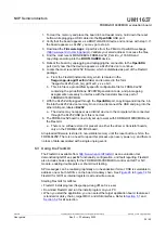
Страница 23: ...on the desktop By default the FlexGUI executable file is installed at C flexgui app des gd31xx exe Installing the device drivers overwrites any previous FlexGUI installation and replaces it with a current version containing the GD31xx drivers However configuration files spi from the previous version remain intact 6 2 Configuring the FRDM KL25Z microcode Figure 15 FRDM KL25Z setup and interface By ...

Страница 24: ...rt labeled KL25Z a The device may not appear as a distinct device to the computer while connected through the KL25Z USB port this is normal 8 The FRDM KL25Z board is now fully set up to work with FRDMGD3160DCMHB and the FlexGUI a There is no software stored or present on either the driver or translator boards only on the FRDM KL25Z MCU board All uploaded firmware is stored in non volatile memory u...

Страница 25: ... by selecting Settings from the File menu Figure 16 GUI settings menu The Loader and Logs settings are shown below Figure 17 Loader settings UM11637 All information provided in this document is subject to legal disclaimers NXP B V 2022 All rights reserved User guide Rev 2 3 February 2022 25 42 ...

Страница 26: ...ss settings by selecting Settings from the File menu The Register Map and Tabs settings are shown below Figure 19 Register map settings UM11637 All information provided in this document is subject to legal disclaimers NXP B V 2022 All rights reserved User guide Rev 2 3 February 2022 26 42 ...

Страница 27: ...bs settings Command Log window The Command Log area informs the user about application events Figure 21 Command Log area UM11637 All information provided in this document is subject to legal disclaimers NXP B V 2022 All rights reserved User guide Rev 2 3 February 2022 27 42 ...

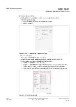
Страница 28: ...ad and automatically poll INTB pins INTA pins are added for GD3160 Control pins set values to a default to a functional state FSENB enable disable fail safe enable EN_PS enables flyback supply on EVB at 17 V VCC on high side and low side FSSTATEL and FSSTATEH set the fail safe state when FSENB is enabled PWML and PWMH set the default state PWM inputs for high side and low side Figure 23 Pins tab f...

Страница 29: ...aults and automatically poll status registers Figure 24 Status tab functionality Analog tab functionality Read and poll ADC values from the high voltage domain Displays raw ADC and converted values Figure 25 Analog tab functionality UM11637 All information provided in this document is subject to legal disclaimers NXP B V 2022 All rights reserved User guide Rev 2 3 February 2022 29 42 ...

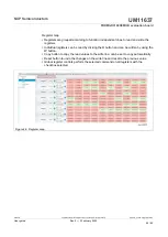
Страница 30: ...he W button Copy button to copy the read values to the write line can be set to copy automatically Reset button to undo the changes on the write line and reset to the previous value Global register controls perform the selected command on all registers with the checkbox selected Figure 26 Register map UM11637 All information provided in this document is subject to legal disclaimers NXP B V 2022 Al...

Страница 31: ...are disabled when not in config mode Provides a more intuitive visual way to set parameters All settings are automatically synchronized with the register controls Figure 27 Gate drive tab UM11637 All information provided in this document is subject to legal disclaimers NXP B V 2022 All rights reserved User guide Rev 2 3 February 2022 31 42 ...

Страница 32: ...urrent sense Provides a more intuitive visual way to set parameters All settings are automatically synchronized with the register controls Figure 28 Current sense tab UM11637 All information provided in this document is subject to legal disclaimers NXP B V 2022 All rights reserved User guide Rev 2 3 February 2022 32 42 ...

Страница 33: ...gmented drive Provides a more intuitive visual way to set parameters All settings are automatically synchronized with the register controls Figure 29 Desat and segmented drive tab UM11637 All information provided in this document is subject to legal disclaimers NXP B V 2022 All rights reserved User guide Rev 2 3 February 2022 33 42 ...

Страница 34: ...vertemperature warning thresholds Provides a more intuitive visual way to set parameters All settings are automatically synchronized with the register controls Figure 30 Overtemperature tab UM11637 All information provided in this document is subject to legal disclaimers NXP B V 2022 All rights reserved User guide Rev 2 3 February 2022 34 42 ...

Страница 35: ...and overvoltage threshold Provides a more intuitive visual way to set parameters All settings are automatically synchronized with the register controls Figure 31 Undervoltage and overvoltage threshold tab UM11637 All information provided in this document is subject to legal disclaimers NXP B V 2022 All rights reserved User guide Rev 2 3 February 2022 35 42 ...

Страница 36: ...d Measurements tab Allows monitoring and graphing of ADC and temperature values Figure 32 Measurements tab UM11637 All information provided in this document is subject to legal disclaimers NXP B V 2022 All rights reserved User guide Rev 2 3 February 2022 36 42 ...

Страница 37: ...egisters can be modified when in configuration mode Figure 33 Status tab Pulse tab Used for double pulse short circuit and PWM testing Select desired T1 T2 and T3 timings for each test type select enable then generate pulses Figure 34 Pulse tab UM11637 All information provided in this document is subject to legal disclaimers NXP B V 2022 All rights reserved User guide Rev 2 3 February 2022 37 42 ...

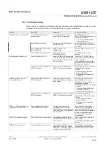
Страница 38: ...ad time is enforced but fault indicates that PWM controls signals are in violation Clear DTFLT fault bit STATUS2 Check PWMHSEL J11 and PWMLSEL J10 are configured to bypass dead time faults Consider adjusting dead time settings on GD3160 Change mandatory PWM dead time setting CONFIG5 Mask dead time fault MSK2 PWM output is good but with persistent fault reported Check for overcurrent OC fault in ST...

Страница 39: ... in power supply circuit for proper value in setting VEE level Clear VCCOV bit STATUS1 to continue VCCOV fault reported on startup Check VCC GNDISO potential PWM is disabled during a VCC overvoltage 20 V nom Tune VCC GNDISO potential to suitable level with power supply set potentiometer R65 Clear VCCOV bit STATUS1 to continue No PWM during short circuit test Check PWMxSEL jumpers Incorrect configu...

Страница 40: ...itions of commercial sale NXP Semiconductors products are sold subject to the general terms and conditions of commercial sale as published at http www nxp com profile terms unless otherwise agreed in a valid written individual agreement In case an individual agreement is concluded only the terms and conditions of the respective agreement shall apply NXP Semiconductors hereby expressly objects to a...

Страница 41: ...alf bridge setup 16 Fig 11 Normal mode SPI for half bridge configuration 18 Fig 12 Daisy chain 1 2 for half bridge configuration 19 Fig 13 Three phase setup 20 Fig 14 Daisy chain 1 6 for three phase board configuration 22 Fig 15 FRDM KL25Z setup and interface 23 Fig 16 GUI settings menu 25 Fig 17 Loader settings 25 Fig 18 Logs settings 26 Fig 19 Register map settings 26 Fig 20 Tabs settings 27 Fig...

Страница 42: ...ion 16 5 1 1 System setup 16 5 1 2 Quick start 17 5 1 3 Normal mode SPI configuration 17 5 1 4 Daisy chain SPI configuration 18 5 2 Three phase configuration 20 5 2 1 System setup 20 5 2 2 Quick start 21 6 Installation and use of software tools 23 6 1 Installing FlexGUI on your computer 23 6 2 Configuring the FRDM KL25Z microcode 23 6 3 Using the FlexGUI 24 6 4 Troubleshooting 38 7 Schematics boar...

Отзывы: