© Safe Fleet | 2022 | All rights reserved
Page
2
Smart-Reach AC Base
Antenna Installation Guide
Smart-Reach AC Base Installation
Follow the procedures in the included
Quick Installation
Guide
and the supplied installation accessories to secure
the Smart-Reach AC Base access point to the location
identified by Safe Fleet engineering professional services.
Access Point Mounting Requirements
• Ensure power, LAN, and antenna status lights are visible
from the selected mounting location.
Connecting the Ethernet cable
Ethernet Cabling Requirements
• Use minimum Category 5e cable (outdoor-rated),
and ensure the RJ45 connector does not have a
boot, or it will not fit into the LAN port.
• Ensure connectors are crimped onto the Ethernet
cable. T568A wiring color code is preferred.
• POE Ethernet cable runs (from AP to POE injector)
cannot exceed 300 feet (100 meters).
• Always test the cable with an Ethernet cable tester
before connecting to equipment
.
1.
Remove the weatherproofing cap from the access
point’s
LAN 1
port (
PoE Input
).
2.
Remove the weatherproofing insert from the port and
discard the center rubber plug.
3.
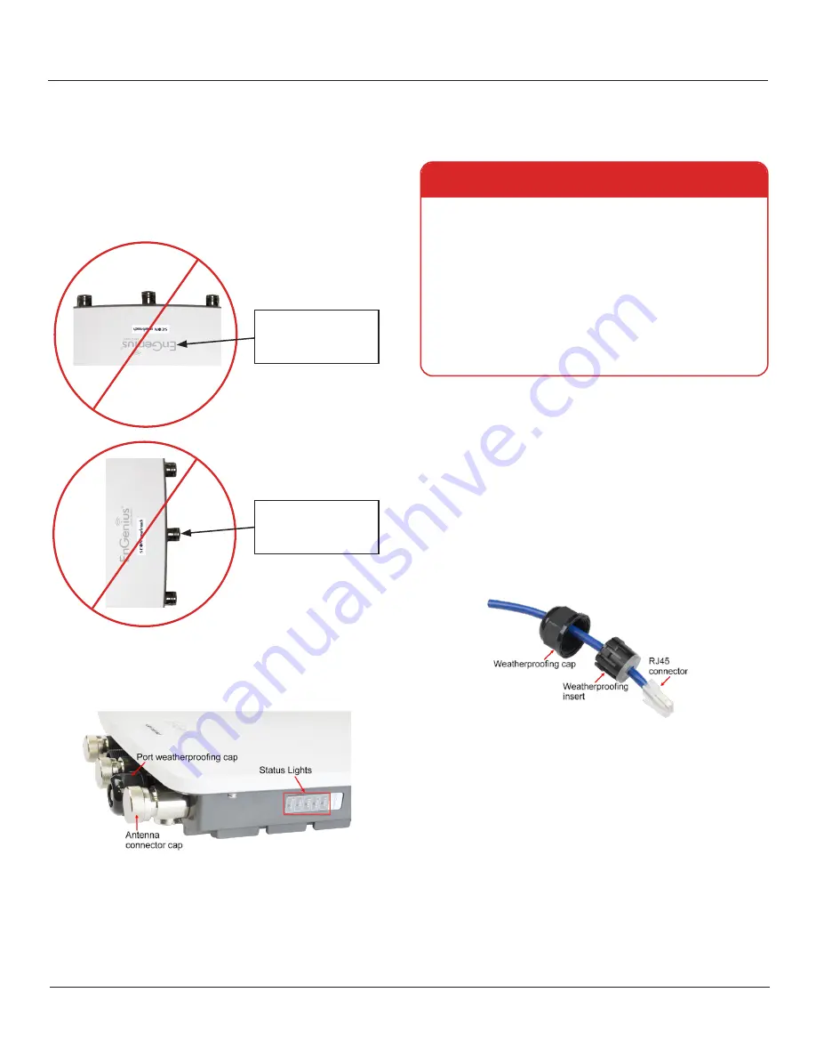
Slide the weatherproofing cap over the cable (threaded
side facing the connector).
4.
Wrap the weatherproofing insert around the cable.
Ensure the larger side of the insert (with the tabs) faces
the weatherproofing cap, as shown in the following
image:
Do not mount upside-
down
: the "EnGenius" logo
should be facing out, and
readable (right-side-up).
Do not mount horizontally
:
antenna connectors/ports
must be at the top and
bottom, not the sides.
5. Plug the RJ45 connector into the
LAN 1
port (
PoE
Input
).
6.
Push the weatherproofing insert into the port.
7.
Thread the weatherproofing cap onto the port
connector.
As an extra layer of security, it is best practice to encase
the whole cap/cable assembly in rubber splicing or
weatherproofing tape.
Ensure the ground cable is properly connected
.


