Fold Here
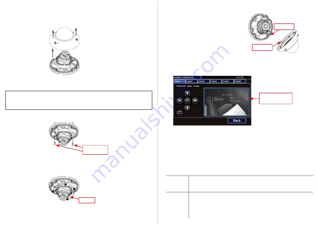
Step 3: Open the Camera
1. Using the security key supplied with the camera, loosen the captive screws on the housing.
2. Lift the housing off of the base.
Step 4: Install the Camera
CAUTION
:
Camera PCB and Wiring
While installing the camera, do not impact the printed circuit board or wiring inside the camera
with screws or screwdriver bits. Damage to the camera can result.
Use the two #10 x 1” self-drilling mounting screws supplied with the camera to attach the
camera to the vehicle.
#10 x 1” self-drilling
mounting screws
Step 5: Aim and Configure the Camera
With the camera connected to the recorder and both powered on, access the recorder using a
monitor connected to the local video out, and set the camera view position.
Gimbal face
With the recorder’s on-screen display showing the camera view, set the camera’s pan, tilt, and
rotate positions.
Step 7: Configuration Settings
1. Open the recorder’s on-screen display
Camera Advanced
tab:
Configuration
Record
Camera
Camera Advanced
2. Click the tab for the camera you want to configure.
3. Click
Set
to display the camera configuration Main Menu.
4. Use the up/down arrows to choose
IR
or
BACKLIGHT
.
A triangle pointer appears to the left of the selected option.
5. Use the left/right arrows to cycle through settings until the desired option appears (for
details, see the table below).
6. When you’re done, use the up/down arrows to select option
4.
EXIT
(
SAVE & END
), then click
Set
to save your settings and close the menu.
7. Click
Back
repeatedly to exit Configuration menus.
Camera Configuration
Main Menu
IR
(Infrared)
OFF
: IR is disabled. Use in product configurations where IR is not required.
ON
(default): IR LEDs illuminate automatically upon sensing a low light
condition.
BACKLIGHT WDR
- Wide Dynamic Range (default): helps reduce glare for scenes with
simultaneous wide variance in lighting
BLC
- Back Light Compensation: helps improve image quality when back lighting
is strong.
OFF
: Shutter speed is based on the light level of the entire image.
Step 6: Replace Camera Dome
1. Fit the dome onto the base,
ensuring the pin
on the dome is aligned with the slot on the
base
before tightening the security screws.
2. Ensure the foam IR boot around the camera
lens is firmly pressed against the inside of the
dome.
3. Use the security key to tighten the captive
screws.
Alignment Pin
Alignment Slot


