

Fold Her
e
Step
7
: Configuration Settings
(
continued
)
Changing IR or Backlight Settings
(
continued
)
IR
(Infrared)
OFF
: IR is disabled. Use in product configurations where IR is not required.
ON
(
default
): IR LEDs illuminate automatically upon sensing a low light condition.
BACKLIGHT WDR
- Wide Dynamic Range (
default
): helps reduce glare for scenes with simultaneous
wide variance in lighting
BLC
- Back Light Compensation: helps improve image quality when back lighting is strong.
OFF
: Shutter speed is based on the light level of the entire image.
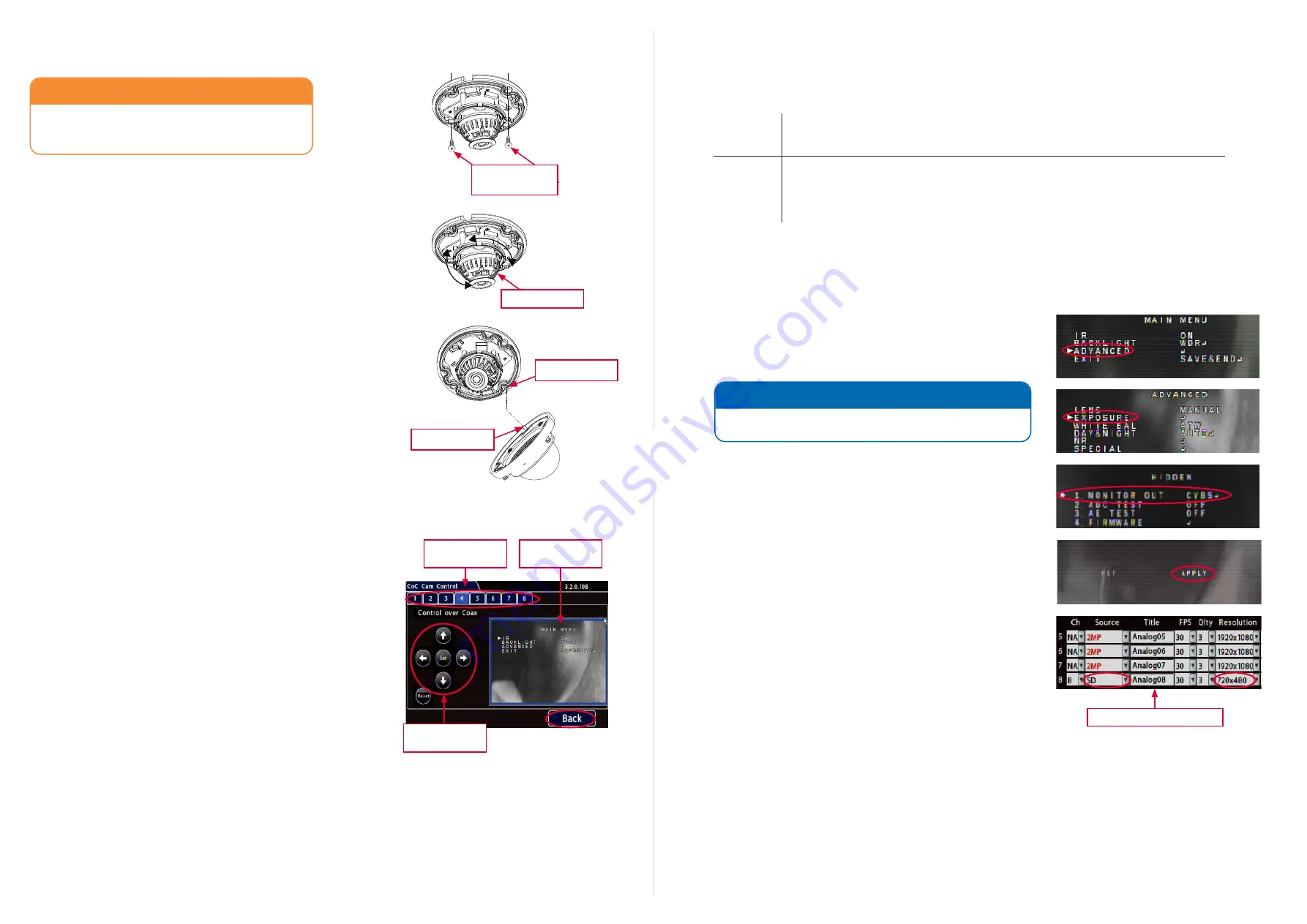
Configuring Video Output Mode (AHD or SDA)
These steps change the video output mode from SDA (CBVS) to AHD
and vice versa. Remember to use the correct video cable for the selected
mode.
1.
Open the
CoC
Main Menu
and select the tab for the channel to
which your camera is connected (for details, see “Accessing the
CoC Main Menu” on the previous page).
2.
Click
twice
to select
ADVANCED
.
A triangle pointer appears to the left of the current selection.
3.
Click
Set
to display the Advanced menu.
4.
Click click
to select
EXPOSURE
.
5.
Click
three times
, then click
Set
.
The
HIDDEN
menu should be displayed.
Note: if the EXPOSURE
menu appears instead, the command failed to execute
: use the
buttons to select
RETURN
, click
Set
, then retry the command.
6.
With
MONITOR OUT
selected,
click
to change the setting from
CVBS
(SDA) to
AHD
or vice-versa.
7.
Click
Set
. The menu screen displays RET (flashing) and APPLY.
8.
Click
to select
APPLY
, which then flashes at the right side of the
screen.
9.
Click
Set
. The camera restarts and the CoC menus close.
9.
Click the
Back
button at the bottom-right of the CoC Cam Control
screen. The
Camera Settings
Analog
tab appears.
10.
In the row for the channel to which your camera is connected, use
the
Source
dropdown menu and select
2MP
or
SD
, depending
upon the selected
MONITOR OUT
setting. Available resolution
values will automatically update.
NOTE: CoC Menu Controls
If menu navigation or item selection (clicks) do not appear to
take effect, you may need to retry the operation.
Step 4: Install the Camera
CAUTION: Camera PCB and Wiring
While installing the camera, do not impact the printed
circuit board or wiring inside the camera with screws or
screwdriver bits. Damage to the camera can result.
Use the two #10 x 1” self-drilling mounting screws supplied with the
camera to attach the camera to the vehicle.
Step 5: Aim and Configure the Camera
1.
With the camera connected to the recorder and both powered
on, access the recorder using a monitor connected to the local
video out.
2.
With the recorder’s on-screen display showing the camera view,
set the camera’s pan, tilt, and rotate positions.
Step 6: Replace the Camera Dome
1.
Fit the dome onto the base,
ensuring the pin on the dome is
aligned with the slot on the base
before tightening the security
screws.
2. Ensure the foam IR boot around the camera lens is firmly
pressed against the inside of the dome.
3.
Use the security key to tighten the captive screws.
Alignment Slot
Alignment Pin
Step
7
: Configuration Settings
Cameras covered by this guide are configured for legacy CCTV recorders.
This section explains how to adjust camera modes on recorders
supporting the CoC (Control over Coax) function. This generally includes
the H-Series recorders.
Accessing the CoC Main Menu
1.
Open the recorder’s on-screen display
CoC Cam Control
screen.
On newer recorders running updated firmware, use the following
navigation through the menu path (
other recorders or older
firmware may utilize a different menu path
):
Configuration
Record
Camera
Analog
CoC Cam Control
2.
Select the tab for the channel to which your camera is connected.
3.
Click
Set
to display the camera CoC Main Menu.
Changing IR or Backlight Settings
1.
In the CoC Main Menu, use
buttons to choose
IR
or
BACKLIGHT
. A triangle pointer appears to the left of the selected
option.
2.
Click
to cycle through settings until the desired option
appears in the right-hand column (
for details, see the table on the
next page
).
3.
When you’re done, use
to select
EXIT
(
SAVE & END
), then
click
Set
to save your settings and close the menu.
4.
Click
Back
repeatedly to exit Configuration menus.
CoC
Main Menu
Camera
channel tabs
CoC menu
controls
#10 x 1” self-drilling
mounting screws
Gimbal face
Camera Settings (Analog tab)


