background image

5110-37MP:  1 of 6;

Rev. 2: 12/03

For questions or concerns, please call the


Safco Consumer Hot Line 

1-800-664-0042

available Monday-Friday 8:00 AM to 4:30 PM (Central Time) (English-speaking operators)

TOOLS REQUIRED:

 Standard Screwdriver

PRODUCT WARRANTY CARD

 is available online at: 

www.safcoproducts.com

TASK MASTER

®

 INDUSTRIAL CHAIR

(19” - 27” Range)

A S S E M B L Y     I N S T R U C T I O N S

New Hope, MN 55428

Visit us on the web:

www.safcoproducts.com

an LDI Company

5110

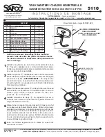
Check all parts against Parts List before

beginning assembly.  Allow all parts to warm to

room temperature prior to assembly.

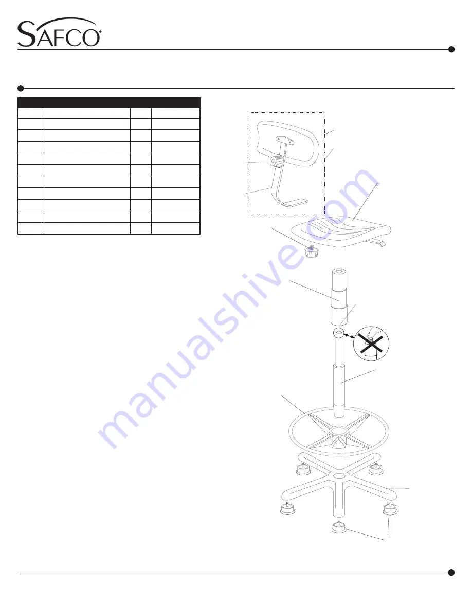
Install a  A  Glide into each of the legs of the  B  Base.

Press firmly into place.  Be sure the glide is inserted

completely into leg for proper stability.

Insert the  C  Cylinder into the base, tapered end down.

Secure the cylinder by applying a little downward pres-

sure (

CAUTION

:  When applying downward pressure,

avoid plastic button at top of cylinder, as pressure will

release pneumatic lift)

Slide  D  Foot Ring on to cylinder (ring side up), posi-

tion at desired height.  Turn knob to secure.  Place  E

Dust Cover over exposed cylinder.

Install the   F  Seat Assembly by aligning the hole on

the underside with the shaft of the cylinder assembly;

push down firmly on seat.

Slide   I  Back Support Bar into bracket on underside of

seat assembly.  Use a standard screwdriver to depress

push button near end of Back Support Bar and slide

Bar until push button locks into bracket.  Remove  H

Knob with Cone Point from parts bag.  Thread Knob

into bracket and tighten to secure Back Support Bar in

proper position.

Make the final chair adjustments following the instruc-

tions on the reverse side.

1

o

o

o

2

3

4

5

o

o

6

o

o

o

Glide

    5

5110-25

Base

    1

5100-04

Cylinder

    1

5110-11

Foot Ring

    1

5110-06

Dust Cover (3 pc set)

    1

5110-14

Seat Assembly

    1

5110-51

Back Assembly

    1

5110-52

Knob with Cone Point     1

6680-78

Back Support Bar

    1

6680-55

Knob with Flat Point

    1

6680-77

A
B
C
D
E

F

G
H

I

J

o

o

o

o

o

o

o

o

o

o

PART NO.

PARTS  LIST

CODE

DESCRIPTION

QTY.

o

A

o

o

B

o

D

E

o

F

o

o

H

G

o

C

Registered U.S. Patent D381,823

o

I

o

J

NOTE:

  REMOVE

PLASTIC CAP

PARTS SHOWN IN BOX

ARE PRE-ASSEMBLED

Содержание TASK MASTER 5110

Страница 1: ...c lift Slide D Foot Ring on to cylinder ring side up posi tion at desired height Turn knob to secure Place E Dust Cover over exposed cylinder Install the F Seat Assembly by aligning the hole on the underside with the shaft of the cylinder assembly push down firmly on seat Slide I Back Support Bar into bracket on underside of seat assembly Use a standard screwdriver to depress push button near end ...

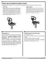
Страница 2: ... AND DEPTH Loosen the backrest height adjustment knob behind the seat Slide the backrest assembly up or down and adjust the height of the back which has a lumbar support curve to it The knob under the seat allows you to adjust the backrest forward and back Sit centered on the seat The curve in the backrest should fit into the small of your back This will reduce the pressure on the spinal discs esp...

Страница 3: ...e Utiliser un tournevis standard pour déprimer le bouton poussoir près la fin du bar du support pour le dossier lit Glisser la bar jusqu à le bouton poussoir fermer dans le crochet Enlever le bouton avec le point du cône H du sac des parties Enfiler le bouton dans le trou du crochet et serrez pour fixer le bar du support pour le dossier lit dans la position propre Faire les derniers règlements de ...

Страница 4: ...de dossier vers le haut ou vers le bas pour régler la hauteur du dossier qui est courbe pour assurer un support lombaire Le bouton qui se trouve au dessous du siège permet de régler le dossier vers l avant ou vers l arrière Pour régler la profondeur du dossier il faut s asseoir avec le corps bien centré sur le siège La courbe du dossier devrait épouser le creux des reins pour réduire la pression s...

Страница 5: ...n cierra en el anaquel Remueva el bulto con el punto del cono H de la bolsa de las partes Enhebre el bulto en el agujero del anaquel y tense para fijar el bar de apoyo para el respaldo en la posición apropiada Para hacer los ajustes finales siga las instrucciones que se encuentran al reverso de esta hoja 5110 37MP 5 of 6 Rev 2 12 03 TASK MASTER SILLA INDUSTRIAL RANGO DE ALTURA DE 48 A 68 CM 19 27 ...

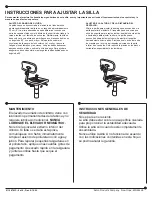
Страница 6: ...a en la parte posterior del asiento El respaldo tiene una curva que sirve de soporte para la región lumbar deslícelo hacia arriba o hacia abajo para ajustar la altura La perilla que se encuentra debajo del asiento permite ajustar el respaldo hacia adelante o hacia atrás Siéntese en el centro de la silla de manera que la curva del respaldo coincida con la parte inferior de su espalda Esto reducirá ...

Отзывы: