


9
XL-SA20018UM-en-US Rev H · 2017-12-14 · Amendments and Errors Reserved · © SAF-HOLLAND, Inc., SAF-HOLLAND, HOLLAND, SAF, and logos are trademarks of
SAF-HOLLAND S.A., SAF-HOLLAND GmbH, and SAF-HOLLAND, Inc.
Disc Brake Inspection
6. Disc Brake Inspection
IMPORTANT:
During removal inspect components for
wear and replace worn components.
Failure to properly support axle during
maintenance could allow axle to fall
which, if not avoided, could result in
death or serious injury.
NOTE:
For further disc brake inspection information, refer
to the latest version of the TMC recommended
practice RP 652–Service and Inspection of Air Disc
Brakes (TMC DVD supplement).
6.1 Pad Wear Inspection
Check the brake pads for proper thickness at regular service
intervals based on vehicle usage. Brake pad inspections should
be carried out at least every three (3) months or 20,000 miles,
whichever comes first, and in accordance with any legal
requirements. Refer to Routine Service Schedule in Section 19.
NOTE:
Regular service intervals may be required more
frequently for severe duty applications. Refer to
Section 19.
A quick visual inspection of the condition of the brake pads
can be performed without removing the wheel:
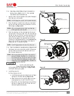
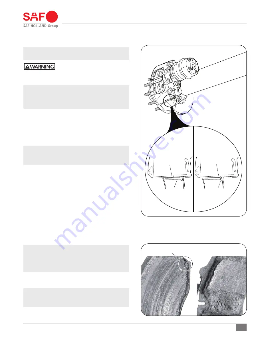
1. Compare the position of the caliper marking to the
carrier marking located on the underside of the caliper
unit
(Figure 7)
.
a.
Figure 7
- View A shows the positions of the two (2)
markings when the brake pads are in good condition.
b.
Figure 7
- View B shows the positions of the two (2)
markings when the wheel MUST be removed for further
inspection of wear to the brake pads and brake rotor.
For further inspection of the brake pads, the wheel and brake
pads MUST be removed. Refer to Section 5 for caliper and service
manual identification.
IMPORTANT:
After inspecting the brake pads, check that
the brake system is functioning properly.
IMPORTANT:
When replacing worn brake pads, ALL pads
on the axle MUST be replaced.
If the friction material of the brake pad is less than 0.43" (2 mm) at
its thinnest area, the brake pad MUST be replaced.
(Figure 10)
.
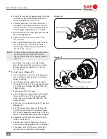
NOTE:
Minor breakouts at the edges are permitted. Major
breakouts on the surface of the brake pad are NOT
permitted
(Figure 8)
.
Figure 8
Figure 7
CARRIER
MARKING
CARRIER
MARKING
PERMITTED
NOT PERMITTED
VIEW A
VIEW B
CALIPER
MARKING
CALIPER
MARKING