


Engineering manual - SAB 193-233-283 S A-frame (including ATEX)
008831 en 2022.02
41/175
The suction stop valve, 101, is bolted to the suction side flange with a non-return valve, 129, in
between. The non-return valve prevents the compressor from rotating backwards during a
standstill period or shutdown.
The discharge gas is sent via the discharge line to the oil separator (193). Gas on the dis-
charge side of the compressor is mixed with a relatively large amount of oil injected into the
compressor for lubrication, cooling and tightening. The oil and the gas must be separated be-
fore the discharge gas proceeds into the refrigeration plant.
The rotary screw compressor uses mating asymmetrical profile helical rotors to provide a con-
tinuous flow of refrigerant vapour. Rotor lobe combination 4+6 male rotor drive is designed for
both high-pressure (TDSH) and low-pressure (TDSB) applications. The compressor incorpo-
rates the following features.
1.
High capacity roller bearings to carry radial loads at both the inlet and outlet ends of the
compressor.
2.
Heavy-duty, four-point angular contact ball bearings to carry axial loads are mounted at
the compressor discharge end.
3.
Balance pistons located at the inlet end of the compressor to reduce axial loads on the
axial load bearings and increase bearing life.
4.
Moveable slide valve to provide fully modulating capacity control from 100% to approx.
10% of full load capacity.
5.
VOLUMIZER ‚ volume ratio control to allow infinitely variable volume ratio from 2.2 to
5.0 during compressor operation for all models.
6.
A hydraulic unloader cylinder to operate the slide stop and slide valve.
7.
Bearing and casing design for 28 bar [400 psi] discharge pressure.
This bar [psi] rat-
ing applies only to the compressor and does not reflect the design pressure of
the various system components.
8.
All bearing and control oil vented to closed thread in the compressor instead of suction
port to avoid performance penalties from superheating suction gas.
9.
Shaft seal design to maintain operating pressure on seal well below discharge pres-
sure, for increased seal life.
10. Oil injected into the rotors to maintain good volumetric and adiabatic efficiency even at
very high compression ratios.
11. Shaft rotation facing compressor, suitable for all types of drives.
12. Dual compressor casing design for very low airborne noise transmission.
13. Integral suction strainer.
14. Flange adaptor for bolting directly to/on motor.
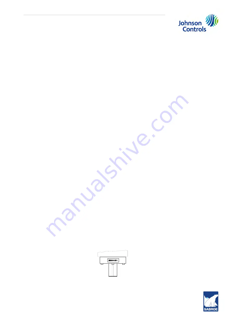
Fig. 17: Shaft rotation
Compressor rotation is
clockwise
when facing the compressor drive shaft. See Fig. 17. Never
operate the compressor in reverse rotation as this will damage the bearings.
COMPRESSOR
Содержание SAB 193 S
Страница 1: ...SAB 193 233 283 S A frame including ATEX Screw compressor units Engineering manual EN...
Страница 2: ......