


8
InstallatIOn cautIOns
Extension Antenna cables — For best results, use high quality coaxial cable with a 50 Ohm
impedance. Specifications will vary by cable manufacturer. For best results, use cable with
minimal attenuation. The longer your cable, the more you will reduce the 100-meter range
between transmitter and receiver antenna. A well-placed pair of extension antennas will
eliminate trouble spots and generally improve overall performance of the wireless.
c
ommon
s
ources
of
rf i
nterference
The typical sources of interference for conventional wireless mics can be high-powered
broadcasters such as radio stations and TV transmitters, or other short-range wireless
devices, including multiple radio microphones operating at the same location (either by
design, or by coincidence), that operate in proximate (or harmonically related) bands. Less
commonly, interference may arise from spurious outputs emitted by electronic equipment
(notably computers, printers, or similar devices with digital clocks), faulty electrical equip
-
ment, neon signs, dimmers and lighting controllers, and so forth.
Many UHF and VHF mics are especially vulnerable because they share the RF spectrum
with the very high-powered transmitters for television. The coming conversion to digital and
high-definition broadcast will increase the problems for UHF and VHF.
The 2.4 to 2.4835 GHz frequency band is not only well above the fundamental (nominal)
transmission frequencies of such strong analog and digital broadcasts, but also high enough
to escape interference problems occurring at the strong first harmonic of even the highest
digital television broadcast. The band is approved worldwide for a variety of uses, including
such diverse transmitters as baby monitors, garage door openers, wireless LANs, amateur
satellite, cordless telephones, etc. Compared to RF broadcast sources like television and
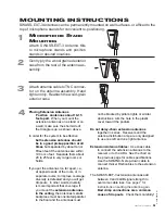
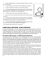
Gain pot
2.
Place the transmitters in the general area where they will be
used, IE the stage.
3.
Connect one of your receivers to the SWM remote software.
4.
Click on the RF Scan button to open the RF scanner.
5.
In the scan range boxes, enter the open channel in both the start
and stop range. For example, if using channel 10 as shown in step 1
above, enter 10 in the “from” and “to” range boxes.
6.
Click the start button to start scanning on channel 10.
7.
Go to one of your extension antennas and turn the gain all the
way down.
8.
Go to the other antenna and turn the gain up until you start seeing
a red or yellow bar on the RF chart on the channel you are scanning.
Now slowly turn the gain down until it just goes away.
9.
Go to the other antenna and repeat the same procedure, turning
the gain down just until the red/yellow bar disappears.
Your extension antennas are now correctly set.


