


Chapter 3. Technical specifications of system Service Manual
– Dena 350
10
Chapter 2.Theory of operation
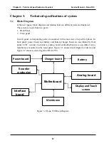
2.1 Different Parts
The system is composed of following parts:
•
Motherboard
•
LED Indicators and membrane
•
LCD and Touch Screen
•
Power Board
•
Battery Charger board
•
Analog Board
•
Recorder Mechanism
•
Interface Board
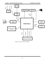
2.1.1 Motherboard
This part of system is identified as "DMY”.
This part consists of main processor, system power supply, LCD controller, Touch Screen driver,
internal flash memory, recorder motor driver and parts related to recorder thermal head.
In Dena 350, main processes are performed by microcontroller on the mainboard. Received data
from Analog Board are processed and at the end, become ready for recording and displaying.
System continuously checks inputs (membrane and touch screen) and in each page, if correct
input received, responses appropriately. In automatic records, Microcontroller saves data on
selected memory (internal flash or SD card) as well as sending commands to thermal head.
Microcontroller is transmitting data to LCD controller continuously.
System power supply is located on motherboard. This part provides necessary voltages for
system by the regulators which mounted on the board.
2.1.2 LED Indicator and membrane keypad
Membrane is an input part of the system which is scanned by microcontroller. User can control
system through this part. LED indicators on the membrane show status of selected power supply
to user.
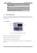
2.1.3 LCD and Touch Screen
Display screen used in Dena 350 is a 5 inch TFT LCD with resolution of 800 × 480 pixels. On
this LCD, a resistive touch screen is mounted which is one of the system inputs. This part is
controlled by microcontroller.
Содержание Dena 350
Страница 1: ...SAADAT Co Service Manual Electrocardiograph D00720 V4 Dena 350...
Страница 22: ...19...


