background image

21

PRIMING THE FUEL SYSTEM

The fuel system has to be primed before initial starting,
after fuel filter change, if the fuel system has been
disconnected, or if the engine has run out of fuel and stops.

Start the priming at the water separator.

1. Loosen the vent plug on top of the separator and let the
   fuel flow until no air is left.
   Re-tighten the vent plug.

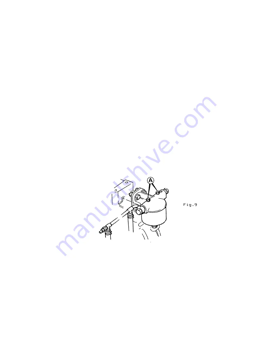
2. Release the bleed screws at the fuel oil filter. Start at
   the inlet side and proceed at the outlet side.
   Pump with the fuel lift pump lever until no further air   
   bubbles are left in the fuel oil. Tighten priming screws.

3. The fuel return line from the fuel oil filter is connected
   to the nozzle leak off lines and is led back to the fuel
   tank.
   Continue pumping for 5-6 strokes to prime the fuel
   injection pump supply.

NOTE.  It is of the greatest importance for trouble-free per-
formance that no air has access to the fuel system.
Make therefore sure that all connections, particularly on the
suction side, are properly tightened.


COOLANT LEVEL CHECK

The engine should be allowed to cool down for some time before
coolant level check.
Be careful when removing the coolant filler cap when the
engine is warm.
Use a rag to protect against scalding.
If necessary, fill up with clean fresh water/anti freeze
mixture.  If the engine has extra header tank, the coolant
level is always checked in the upper tank.

Содержание L2.093LB

Страница 1: ...REVISED NOVEMBER 2000 SABB L DIESEL OPERATORS HANDBOOK FOR L2 093LB L3 139LB L4 186LB LIFEBOAT ENGINE SABB MOTOR A S P O Box 7170 5020 BERGEN NORWAY Telefon 47 55348800 Telefax 47 55348801 e mail firm...

Страница 2: ...____________________________________ 12 STARTING WITH EMERGENCY EL STARTER _________________________________ 13 EMERGENCY STARTING ___________________________________________________________ 13 EMERGE...

Страница 3: ...DAVIS OR IN FREE FALL RIG ________________________________________________ 26 GENERAL PRECAUTIONS REGARDING ELECTRIC SYSTEM ___________________ 26 FAULT FINDING SCHEME _______________________________...

Страница 4: ...ery when working on the engine All drive belts must receive regular attention Keep electrical contacts free from corrosion etc by smearing them with petroleum jelly Batteries under charge release expl...

Страница 5: ...st every effort is made to ensure the accuracy of the particulars contained within this publication neither the Manufacturer Distributor or Dealer shall in any circumstances be held liable for any ina...

Страница 6: ...6 STARBOARD PORTSIDE VIEW ENGINE...

Страница 7: ...Header Tank 10 Exhaust Flange 11 Coolant Outlet 12 Shaft Extension 13 Stop Lever 14 Lubricating Oil Filter 15 Oil Filler Cap Crankcase Door 16 Stop Solenoid 17 Fuel Lift Pump 18 Fuel supply 19 Thermos...

Страница 8: ...1 860 Firing Order 1 2 1 2 3 1 3 4 2 Compression Ratio 18 5 1 Output at 3000 RPM kW bhp 19 14 2 21 6 29 29 39 Output Reference Continuous Fuel Oil Consumption l h 3 9 5 9 7 8 Lub Oil Consumption l 24...

Страница 9: ...ng it The engine will automatically disengage the excess fuel position when the engine runs up to speed LUBRICATION SYSTEM Lub Oil Pressure Min 1 0 bar at idle Min 2 5 bar at 3000 rpm Oil Sump Capacit...

Страница 10: ...an engine block heater is part of the equipment The engine heater should always be energised in environments where the temperature is 15 or lower The engine heater is 300 W and the voltage is 42 V An...

Страница 11: ...TO IGNITION POSITION WHEN THE ENGINE STARTS WARNING LAMPS SHOULD NOW BE OFF IF THE BATTERY IS IN POOR CONDITION TURN THE BATTERY SWITCH FROM BATTERY NO 1 TO BATTERY NO 2 AND REPEAT THE STARTING PROCE...

Страница 12: ...buzzer will sound STARTING 1 Before attempting to start the engine the operator should be familiar with the safety precautions as described earlier 2 Move the speed gearbox lever into max speed posit...

Страница 13: ...el housing The starter panel is mounted in front and on port side of the engine EMERGENCY STARTING If the main starting system fails to work open the engine room cover and read the starting instructio...

Страница 14: ...perature it may be necessary to give some extra shots even after ignition to boost the process CAUTION NEVER OPERATE GLOW PLUG WHEN USING ETHER PUMP OPERATION If one or more alarm lamps do not go out...

Страница 15: ...15 SPRING STARTER CAUTION NEVER OPERATE GLOW PLUG WHEN USING ETHER PUMP...

Страница 16: ...exhaust manifold bolts and nuts Check belt tension see ALTERNATOR BELT TENSION Check lubrication oil and coolant level ROUTINE MAINTENANCE PERIODS PERIOD ATTENTION After the First 15 Hours or after th...

Страница 17: ...less detergency than specified API CD Series 3 or MIL L 2104C D oils can inhibit the running in process in new or reconditioned engine but can be recommended for engines running at high load factor pa...

Страница 18: ...ump Bolt 21 0 15 5 Injector Pipe Nuts 28 5 21 0 Fuel Pump Clamp 33 9 25 0 Starter Motor Screw 40 7 30 0 Fuel Pump Delivery Valve Holder 47 5 35 0 Flywheel Bolt 67 8 50 0 Flywheel Housing Screw 78 6 58...

Страница 19: ...oil level should always be checked before starting The level should never be allowed to fall below lower mark Note that the marks indicate correct level when the engine has appr horizontal position T...

Страница 20: ...lean oil to the oil filter sealing gasket Screw on the new oil filter canister until the sealing gasket abuts the filter head and tighten a further half turn GEARBOX OIL CHECK AND CHANGE Unscrew the d...

Страница 21: ...3 The fuel return line from the fuel oil filter is connected to the nozzle leak off lines and is led back to the fuel tank Continue pumping for 5 6 strokes to prime the fuel injection pump supply NOTE...

Страница 22: ...ion 19 Loosen the rubber bend between the thermostat housing and the water cooled exhaust manifold or header tank on L4 139 LB Unscrew the thermostat housing bolts and remove the housing with thermost...

Страница 23: ...fter consulting SABB MOTOR A S The idling speed is adjusted with the adjusting screw A see Fig 11 Fig 11 VALVE CLEARANCE ADJUSTMENT The engine is fitted with hydraulic tappets and therefore no adjustm...

Страница 24: ...ntinuously used the heater element is subject to burning and should be checked yearly or if the heating does not work Drain the coolant through the drain plug Disconnect the leads and unscrew the heat...

Страница 25: ...ould be added only before charging the battery Keep the battery terminals clean and coat with petroleum jelly If the battery is of the maintenance free type without filler plugs the condition may be c...

Страница 26: ...osition Always check that cables are connected to their correct terminals before reconnecting the batteries A reversal of polarity or short circuit will destroy diodes and transistors in the alternato...

Страница 27: ...b Stop solenoid linkage is loose c Defect stop solenoid DESCRIPTION OF THE ELECTRICAL OPERATED STOP START SYSTEM The lever A has two functions 1 To stop the engine The engine is stopped when the lever...

Страница 28: ...ed and the plunger retracts As soon as it BOTTOMS the internal switch disconnects the high current winding and the plunger is kept retracted by the hold coil The stop solenoid is secured by an automat...

Страница 29: ...e sticking or corroded It may be a good remedy to remove the stop solenoid plunger and spray some contact cleaner f inst crc 2 26 against the bottom The nylon switch pin should be loose in its bore If...

Страница 30: ...rect part name and part number When ordering always state full details 1 Engine type and Serial no Identification plate Fig 15 2 Part name and part No See page No 5 and 6 3 Quantity 4 Full address nam...

Отзывы: