background image

12

ASSEMBLY

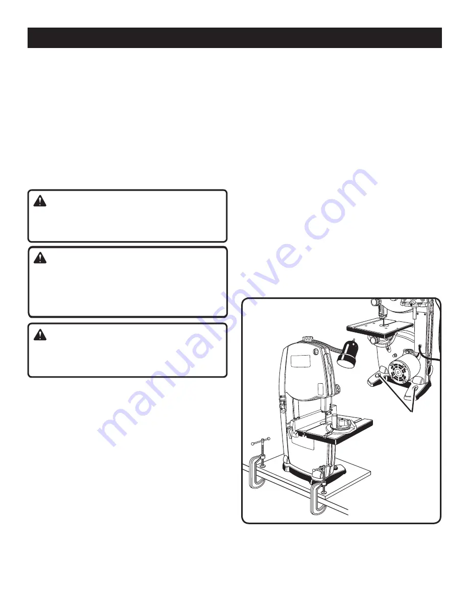
HOLES IN  

SAW BASE

Fig. 5

UNPACKING

This product requires ass

embly.

  Carefully remove the tool and any accessories from the 

box. Place it on a level work surface.


NOTE: 

This tool is heavy. To avoid back injury, lift with 

your legs, not your back, and get help when needed.

  Inspect the tool carefully to make sure no breakage or 

damage occurred during shipping. 

  Do not discard the packing material until you have care-

fully inspected and satisfactorily operated the tool.

  If any parts are damaged or missing, please call 1-800-

525-2579 for assistance.

WARNING:

If any parts are damaged or missing, do not operate this 
tool until the missing parts are replaced. Failure to do so 
could result in possible serious personal injury.

WARNING:

Do  not  attempt  to  modify  this  tool  or  create  accesso-
ries not recommended for use with this tool. Any such 
alteration or modification is misuse and could result in a 
hazardous condition leading to possible serious personal 
injury.

WARNING:

Do  not  connect  to  power  supply  until  assembly  is 
complete.  Failure  to  comply  could  result  in  accidental 
starting and possible serious personal injury.

MOUNTING BAND SAW TO WORKBENCH

If the band saw is to be used in a permanent location, we 
recommend  that  you  secure  it  to  a  workbench  or  other 
stable  surface.  When  mounting  the  saw  to  a  workbench, 
holes should be drilled through the supporting surface of 
the workbench.

  Each  hole  in  the  saw  base  should  be  bolted  securely 

using bolts, lock washers, and hex nuts (not included). 

  Place band saw on the workbench. Using the saw base 

as a pattern, locate and mark the holes where the band 
saw is to be mounted.

  Drill holes through the workbench.

  Place band saw on the workbench aligning holes in the 

saw base with the holes drilled in the workbench.

  Insert bolts (not included) and tighten securely with lock 

washers and hex nuts (not included).

  NOTE:

 All bolts should be inserted from the top. Install 

the lock washers and hex nuts from the underside of the 
bench.

Supporting surface where band saw is mounted should be 
examined carefully after mounting to insure that no move-
ment during use can result. If any tipping or walking is noted, 
secure  workbench  or  support  surface  before  beginning 
cutting operation.

CLAMPING BAND SAW TO WORKBENCH

See Figure 5. 

If the band saw is to be used as a portable tool, it is recom-
mended that you fasten it permanently to a mounting board 
that can easily be clamped to a workbench or other supporting 
surface. The mounting board should be of sufficient size to 
avoid tipping of saw while in use. Any good grade plywood 
or chipboard with a 3/4 in. thickness is recommended.

  Mount saw to board using holes in saw base as a template 

for hole pattern. Locate and mark the holes where the 
band saw is to be mounted.

  Follow the last three steps in the section 

Mounting Band 

Saw to Workbench,

 shown above. 

If lag bolts are used, make sure they are long enough to 

Содержание BS902

Страница 1: ...dability ease of operation and operator safety When properly cared for it will give you years of rugged trouble free performance WARNING To reduce the risk of injury the user must read and understand the operator s manual before using this product Thank you for your purchase OPERATOR S MANUAL 9 in 229 mm BAND SAW BS902 ...

Страница 2: ...0 days Batteries are warranted for two years HOW TO GET SERVICE Just return the power tool properly packaged and postage prepaid to an Authorized Service Center You can obtain the location of the Service Center nearest you by contacting a service representative at One World Technologies Inc P O Box 1207 Anderson SC 29622 1207 by calling 1 800 525 2579 or by logging on to www ryobitools com When yo...

Страница 3: ...practical It s is safer than using your hand and frees both hands to operate the tool DO NOT OVERREACH Keep proper footing and balance at all times MAINTAIN TOOLS WITH CARE Keep tools sharp and clean for better and safer performance Follow instructions for lubricating and changing accessories DISCONNECT TOOLS When not in use before servicing or when changing attachments blades bits cutters etc all...

Страница 4: ... key HOLD THE WORKPIECE firmly against the saw table TO AVOID ACCIDENTAL BLADE CONTACT minimize blade breakage and provide maximum blade support always adjust the blade guide assembly to just clear the workpiece KEEPBLADESCLEAN SHARP ANDWITHSUFFICIENT SET Sharp blades minimize stalling and kickbacks ALWAYS TURN OFF SAW before disconnecting it to avoid accidental starting when reconnecting to a pow...

Страница 5: ...speed orbits etc per minute Do not expose to rain or use in damp locations To reduce the risk of injury user must read and understand operator s manual before using this product Eye Protection Precautions that involve your safety Failure to keep your hands away from the blade will result in serious personal injury Wet Conditions Alert min Per Minute Class II Construction no No Load Speed Direct Cu...

Страница 6: ...he product to the nearest AUTHORIZED SERVICE CENTER for repair When servic ing use only identical replacement parts WARNING To avoid serious personal injury do not attempt to use this product until you read thoroughly and understand com pletely the operator s manual If you do not understand the warnings and instructions in the operator s manual do not use this product Call Ryobi customer service f...

Страница 7: ...one shown Fig 1 EXTENSION CORDS Use only 3 wire extension cords that have 3 prong ground ing plugs and 3 pole receptacles that accept the tool s plug When using a power tool at a considerable distance from the power source use an extension cord heavy enough to carry the current that the tool will draw An undersized extension cord will cause a drop in line voltage resulting in a loss of power and c...

Страница 8: ...ng dropped into the blade or being placed inadvertently in contact with the blade Workpiece or Material The item on which the operation is being done Worktable Surface where the workpiece rests while performing a cutting drilling planing or sanding operation Anti Kickback Pawls radial arm and table saws A devise which when properly installed and maintained is designed to stop the workpiece from be...

Страница 9: ...CK KNOB DUST EXHAUST PORT TRACKING KNOB ANGLE ADJUSTMENT KNOB RAPIDSET BLADE TENSION LEVER WORKLIGHT Table Size 11 13 16 in x 11 13 16 in Input 120 V 60 Hz AC only 2 5 Amps No Load Speed 3 000 FPM 1 524 cm s Dust Port 2 1 4 in Net Weight 37 lbs Fig 2 TRACKING VIEW WINDOW SAW BLADE SWITCH AND SWITCH KEY LATCH BLADE TENSION KNOB LATCH RIP FENCE MITER GAUGE SAW TABLE BLADE GUARD TRACKLOCK BLADE GUIDE...

Страница 10: ... area for safer more accurate cuts KNOW YOUR BAND SAW The safe use of this product requires an understanding of the information on the tool and in this operator s manual as wellasaknowledgeoftheprojectyouareattempting Before use of this product familiarize yourself with all operating features and safety rules ANGLE ADJUSTMENT KNOB Tilts the saw table for bevel cutting BLADE GUARD Protects the oper...

Страница 11: ...REW TABLE ALIGNING BOLT WASHER WING NUT RIP FENCE WING SCREW WORKLIGHT Hex Key 4 mm 1 Rip Fence 1 Miter Gauge 1 Saw Table 1 Wing Screw 1 Wing Nut 1 Table Aligning Bolt 1 Flat Head Screw 3 Worklight 1 Washer 1 Switch Key 1 Operator s Manual not shown 1 SWITCH KEY The following items are included with the tool WARNING The use of attachments or accessories not listed might be hazardous and could caus...

Страница 12: ...drilled through the supporting surface of the workbench Each hole in the saw base should be bolted securely using bolts lock washers and hex nuts not included Place band saw on the workbench Using the saw base as a pattern locate and mark the holes where the band saw is to be mounted Drill holes through the workbench Place band saw on the workbench aligning holes in the saw base with the holes dri...

Страница 13: ...e Figures 6 and 7 Standing at the front of the band saw slide the saw table pass the blade and through the slot moving from the right side of the saw table to the left Align the screw holes in the saw table with the holes in the saw table bracket Using the phillips screws attach the saw table to the saw table bracket Tighten phillips screws securely Attach the table aligning bolt washer and wing n...

Страница 14: ...ION See Figures 9 and 10 Turn off and unplug the saw Remove the switch key Before using the band saw turn the blade tension knob on the top of the saw clockwise to engage tension NOTE Adjustments of blade tension can be made at anytime Another method of checking blade tension has to do with the sound the blade makes when plucked like a guitar string Pluck the back straight edge on the coasting sid...

Страница 15: ...ires Rotate the upper wheel by hand in a clockwise direction for a few more turns Make sure the blade stays in the same location on the tires Readjust if necessary until blade is tracking properly Close front cover and relatch NOTE The 1 8 in blade may not track properly in the center of the wheel It may be better to track this blade on the back half of the upper wheel ATTACHING THE WORKLIGHT See ...

Страница 16: ...not force the work allow the blade to cut The smallest diameter circle that can be cut is determined by blade width A 1 4 in wide blade will cut a minimum diameter of 1 1 2 in a 1 8 in wide blade will cut a minimum diameter of 1 2 in Keep your hands away from the blade Do not hand hold pieces so small your fingers will go under the blade guard Avoid awkward operations and hand positions where a su...

Страница 17: ...nt down toward the saw table that the blade guides thrust bearings and blade tension are properly adjusted that the blade guide knob is tight and that no parts have excessive play To avoid accidental blade contact minimize blade breakage and provide maximum blade support always adjust the blade guide assembly to just clear the workpiece Use only recommended accessories With the exception of the wo...

Страница 18: ... slot rotate the gauge until the desired angle is reached on the index scale Retighten the lock knob NOTE For convenience store the miter gauge in the slot provide on the back of the band saw USING THE RIP FENCE See Figure 15 From either side of the saw table slide the rip fence onto the saw table Check for a smooth gliding action Push the locking handle down to automatically align and secure the ...

Страница 19: ...ur workpiece Carefully wipe in the same direction the teeth are pointing so the rag does not catch on the teeth of the saw blade NOTE The blade may need to be turned inside out if the teeth are pointing in the wrong direction Hold the blade with both hands and rotate it inward With the teeth of the blade toward the front of the saw and facing downward place the blade through the lower blade guides...

Страница 20: ...iece Turn the lock knob counterclockwise to unlock the blade guide assembly As a guide use a scrap piece of the same wood you are about to cut to set the height of the blade guide assembly Adjust the blade guide assembly by turning the blade guide knob Lock blade guide assembly in place by turning the lock knob clockwise Always lock the blade guide assembly in place before turning on the band saw ...

Страница 21: ...g screw Move the thrust bearing to within 1 64 in 0 4 mm of the blade Tighten the thrust bearing screw securely Repeat this procedure on the lower thrust bearing located below the saw table Replace the blade guard if no additional adjustments are to be made To Adjust Blade Guide Support Remove the blade guard by loosening the two phillips screws Adjust the position of the blade guide assembly Loos...

Страница 22: ...t If operation is dusty also wear a dust mask GENERAL MAINTENANCE Avoid using solvents when cleaning plastic parts Most plastics are susceptible to damage from various types of commercial solvents and may be damaged by their use Use clean cloths to remove dirt dust oil grease etc WARNING Do not at any time let brake fluids gasoline petroleum based products penetrating oils etc come in contact with...

Страница 23: ...Do not use a sharp knife or any kind of solvent Replacing tires Open front cover and remove saw blade See section on Installing and Adjusting the Blade page 17 Pry the worn tire away from the wheel carefully Stretch the new tire around the wheel Replace the saw blade and close the front cover BRUSHES See Figure 23 There is a brush located inside the saw housing next to the lower wheel It helps pro...

Страница 24: ...ade caused by cutting 2 Use correct cutting technique too small radius or turning the See section Operation material too fast when cutting 3 Thrust bearings scarred or not 3 Replace the thrust bearings rotating Saw is noisy when running 1 Too much blade tension 1 Adjust tension See Adjustments section Adjusting Blade Tension 2 Blade guides and bearings 2 Adjust upper and lower blade are in contact...

Страница 25: ...25 NOTES ...

Страница 26: ...d Service Centers MODEL NO AND SERIAL NO The model number of this tool will be found on a plate attached to the motor housing Please record the model number and serial number in the space provided below HOW TO ORDER REPAIR PARTS When ordering repair parts always give the following information MODEL NUMBER SERIAL NUMBER BS902 ONE WORLD TECHNOLOGIES INC 1428 Pearman Dairy Road Anderson SC 29625 Phon...

Отзывы: