Ruskin Z2000RT Скачать руководство пользователя страница 4


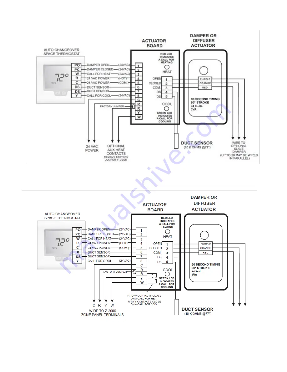
SYSTEM WIRING DIAGRAMS


Stand-Alone Modulating Damper  or  Diffuser System


Z2000 Modulating Zone Control System


WIRE TO OPTIONAL 

TRACER 

DSAMPER(S) 

 (UP TO 20 MAY BE 

WIRED IN 

PARALLEL) 

Z2000RT 

WIRE TO OPTIONAL 

TRACER 

DAMPER(S) 

 (UP TO 20 MAY BE 

WIRED IN 

PARALLEL) 

Z2000RT 

Содержание Z2000RT

Страница 1: ...one Control Solutions Installation Maintenance Manual Model Z2000RT Wall Mount Thermostat II Z2000RT 613 New ALL STATED SPECIFICATIONS ARE SUBJECT TO CHANGE WITHOUT PRIOR NOTICE OR OBLIGATION RUSKIN 2013 ...

Страница 2: ...sert a small coin in the release slot located on the bottom of the thermostat Gently twist the coin to release the thermostat from the sub base Avoid twisting the case as this may stress the LCD and cause it to crack or bend the terminal pin connectors TERMINAL DESIGNATIONS The Z2000RT has dedicated screw terminals located on the sub base to facilitate ease of wiring to the actuator logic card mou...

Страница 3: ...may warp causing improper seating of the thermostat connecting pins to the terminal blocks Use a properly sized screwdriver and terminate each wire to its dedicated terminal Do not over tighten the terminal screws Check to see that all wires are landed correctly and dressed properly to prevent any shorts SWITCH FUNCTIONS The Z2000RT contains a set of dip switches numbered 1 through 8 Only dip swit...

Страница 4: ...lone Modulating Damper or Diffuser System Z2000 Modulating Zone Control System 4 WIRE TO OPTIONAL TRACER DSAMPER S UP TO 20 MAY BE WIRED IN PARALLEL Z2000RT WIRE TO OPTIONAL TRACER DAMPER S UP TO 20 MAY BE WIRED IN PARALLEL Z2000RT ...

Страница 5: ...to the thermostat The LCD Display will momentarily display all icons as shown in Figure 1 ENTERING THE SETUP MENU Press twice and hold the SETUP key until the word DAMPER appears on the LCD screen as indicated on Figure 2 SETTING THE MINIMUM DAMPER POSITION Press the SETUP key again and the LCD will display the minimum damper position The factory default is 10 which means the damper is driven 90 c...

Страница 6: ...amper blade fully open or fully closed This is a critical step in the Z2000RT setup since the thermostat can be used with a variety of 24 Volt actuators If you are unsure of the actuator speed place the actuator in the fully closed position and then apply 24 Volts to common and normally open The time it takes to drive the damper blade fully open equals the actuator speed setting Figure 9 SETTING T...

Страница 7: ... status points UNIT Displays the HVAC unit number assigned to thermostat ZONE Displays the thermostat zone number DUCT Displays the duct temperature DAMPER Displays the damper position in one degree increments 0 fully closed and 100 fully open THERMOSTAT OPERATION The Z2000RT is designed to provide accurate but simple temperature control for the user When the thermostat is not calling only the spa...

Страница 8: ...ng Temperature 23 F to 122 F Operating RH 0 95 non condensing Size 4 7 16 W x 4 1 16 H x 7 8 D LCD Display Size 2 3 4 W x 1 7 8 H Temperature Sensor 10K NTC type 3 Accuracy 1 F 77 F Display Resolution 1 F Control Range 36 F to 96 F Back Light Blue EL Electro Luminescent Back Light Life 3 000 hours to half brightness Communications Protocol Modbus Approvals FCC Part 15 Pending C tick Warranty 5 yea...

Отзывы: