background image

25 

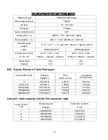
SPECIFICATION(HWP20000Y1D/Y2D 

Rated line pull 

20000 lbs (9072 kgs) 

Motor displacement 

100ml/r 

Oil flow 

15

75L/min 

Pressure 

17.5Mpa 

Gear reduction ratio 

39:1 

Cable (Dia.

×

 L) 

Ø9/16

×

157 

‘ (Ø14mm

×

48m) 

Drum size(Dia.

×

 L) 

Ø5.4 

×

12.4

” (Ø138mm

×

316mm) 

Mounting bolt 

pattern 

17.0 

×

2.5 

“ 

×

7.6 

“ (431mm

×

64mm

×

192mm) 8-M14 

Item 

HWP20000Y1D 

HWP20000Y2D 

Overall dimensions 

(L

×

W

×

H) 

30.9"

×

15.4"

×

12.6" 

784mm 

×

390mm 

×

320mm 

35.0"

×

15.4"

×

12.6" 

889mm 

×

390mm 

×

320mm 

Net weight 

Ibs(kgs) 

360 

163 

360 

163 

Pull , Speed, Pressure, Flow (First layer) 

Line pull lbs (kgs) 

Pressure 

Mpa(Psi) 

Flow 

G/min (L/min) 

Line speed 

ft/min(m/min) 

2.5(362.6) 

4.0(15) 

5.9(1.8) 

4000(1814)


4.2(609.1) 

7.9(30) 

11.8(3.6) 

8000(3629) 

8.5(1232.8) 

13.2(50) 

19.7(6.0) 

15000(6804) 

14.0(2030.5) 

15.9(60) 

23.6(7.2) 

20000(9072) 

17.5(2538.1) 

19.9(75) 

29.5(9.0) 

Line pull, cable capacity and the line speed per layer 

Layer of wire 

rope 

Rated line pull 

lbs(kgs) 

Total rope on drum 

ft (m) 

20000(9072) 

33.8(10.3) 

16889(7661) 

73.8(22.5) 

14615(6629) 

117.8(35.9) 

12881(5843) 

157.5(48.0) 

Содержание HWP20000 Series

Страница 1: ...HYDRAULIC WINCH HWP X20000 SERIES Assembly Operating Instructions ...

Страница 2: ...G 13 WINCH ASSEMBLY DRAWING HWP20000 SERIES 14 WINCH PARTS LIST HWP20000 SERIES 15 WINCH ASSEMBLY DRAWING HWX20000 SERIES 16 WINCH PARTS LIST HWX20000 SERIES 17 OUTLINE DIMENSIONAL DRAWING 18 SPECIFICATION HWP20000U A U3 A3 20 SPECIFICATION HWP20000U1 A1 U2 A2 21 SPECIFICATION HWP20000YP Y3P 22 SPECIFICATION HWP20000Y1P Y2P 23 SPECIFICATION HWP20000YD Y3D 24 SPECIFICATION HWP20000Y1D Y2D 25 SPECIF...

Страница 3: ...llowing symbols for caution warning and danger Pay particular attention to the notes preceded by these symbols as they are written for your safety Ultimately safe operation of this device rests with you the operator This indicates a potentially hazardous situation which if not avoided may result in minor or moderate injury This notation is also used to alert you against unsafe practices This indic...

Страница 4: ...ean dry and free from oil and grease at all times WARNING Disconnect switch Unplug switch when not in use WARNING Stay alert Watch what you are doing use common sense Do not operate any tool when you are tired WARNING Check for damaged parts Before using any tool any part that appears damaged should be carefully checked to determine that it will operate properly and perform its intended function C...

Страница 5: ...secure the item Do not rely on the winch to hold it for an extended period WARNING Examine winch before using Components may be affected by exposure to chemicals salts and rust WARNING Never operate winch if cable shows any signs of weakening such as knotting or kinking WARNING Do not cross over or under cable when the winch is under load WARNING Do not move your vehicle with the cable extended an...

Страница 6: ...provide you with the name of a dealer near you If you will utilize the mounting channel you must ensure that it is mounted on a flat surface so that the three major sections motor drum and gear housing are properly aligned Proper alignment of the winch will allow even distribution of the full rated load 2 Start by connecting the roller fairlead to the mounting channel using 2 each of the cap screw...

Страница 7: ...reme such as an exhaust manifold or turbo Lines should not be allowed to rub on any abrasive or vibrating surfaces In some applications 90 fittings on the directional valve and motor or balance valve are necessary to make hose mounting more flexible After plumbing has been laid out on vehicle install o ring fittings supplied to valve Torque tight Do not over tighten any fittings Install o ring fit...

Страница 8: ...6 U type A type IN OUT The mounting drawing of U type OUT IN The mounting drawing of A type IN OUT ...

Страница 9: ...allation illustration Air actions clutch installation illustration Air clutch for Free spool Air clutch for free spool and two speed HWP20000U A YP YD Manual clutch operation of two speed HWP20000U1 A1 Y1P Y1D Air clutch operation of single speed ...

Страница 10: ...ch is loaded and working Do not clutch out HWP20000U2U A2Y2P Y2D Air and manual mixed clutch operation of single speed WARNING 1 Pressure should not below 87psi 2 When winch is loaded and working Do not clutch out 3 Clutch must be fully engaged before winching HWP20000U3 A3 Y3P Y3D Air clutch and air actions operation of two speed ...

Страница 11: ...ow are the directions on how to purge the hydraulic system 1 Start the engine 2 Power the winch to draw out about 5 feet of cable 3 Shut down the engine 4 Check the fluid level and fill as needed 5 Repeat steps 1 through 4 as necessary 6 Start the engine 7 Move the cable into the desired position 8 Turn the wheels on the vehicle from the right lock to the left lock positions five times to help ble...

Страница 12: ...ply two kinds of flow based on the difference in demand One type of flow will be constant and should be used with the steering system The other will provide higher pressure and is for engineering use Caution Hydraulic system needs an relief valve to make sure the system is safe If there is not relief valve in the system it would be serious danger and the system can t operation If your winch drived...

Страница 13: ...o 15000lbs Heavy Blanket place on the cable to absorb energy should the wire rope break RIGGING TECHNIQUES Self Recovery Locate a suitable anchor such as a strong tree trunk or boulder Always use a sling as an anchor point CAUTION Do not attach the clevis hook back onto the cable as this could cause damage to the cable As shown in Fig 3 1 CAUTION Do not winch from an acute angle as the wire rope w...

Страница 14: ...LACEMENT If the wire rope has become worn or is beginning to show signs of strands breaking it must be replaced before being used again 1 Turning clutch to the Free Spool position 2 Extend cable assembly to its full length Note how the existing cable is connected to the drum 3 Remove old cable assembly and attach new one as the ld cable connected to the drum Insert the end of the new rope and secu...

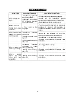
Страница 15: ... qualified technician needed to check and repair Winch drum runs slowly or without normal power Insufficient pressure or oil flow Insufficient fluid in the system Wrong winch working direction Bump is not suitable or defective Change a new one or a suitable one Check fluid level Add fluid until full Change the connection of balance valve and motor Winch brake not working normally Hydraulic pressur...

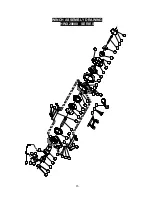
Страница 16: ...14 WINCH ASSEMBLY DRAWING HWP20000 SERIES 2 3 1 4 5 6 12 13 15 10 11 16 17 18 13 19 20 21 22 23 24 25 26 27 7 8 9 14 28 38 39 40 33 34 35 36 35 11 10 6 7 8 9 37 29 30 31 32 27 3 ...

Страница 17: ... 17 HP2000015 1 Screw M8 x 10 18 HP2000300 1 1 Drum Assembly Used in YP YD series HP2000300 2 1 Drum Assembly Used in U A series 19 HP2000016 24 Screw M8 x 35 20 HP2000017 24 Lock Washer Φ8 21 HP2000018 1 End Bearing 22 HP2000019 1 Gear Ring 23 HP2000400 1 Gear Carrier Assembly Output 24 HP2000500 1 Cam Gear Input 25 HP2000017 12 Lock Washer Φ8 26 HP2000020 12 Screw M8 x 20 27 HP2000600 1 1 Gear C...

Страница 18: ...16 WINCH ASSEMBLY DRAWING HWX20000 SERIES 2 3 1 4 5 6 12 13 15 10 11 16 17 18 13 19 20 21 22 23 24 25 26 28 7 8 9 14 29 34 35 36 11 10 6 7 8 9 31 32 30 37 38 39 40 39 41 33 27 ...

Страница 19: ...ta Used in YP series HX2000014 2 1 Back Mounting Plata Used in YD series 17 HX2000015 1 Screw M8 x 10 18 HX2000300 1 1 Drum Assembly Used in YP series HX2000300 2 1 Drum Assembly Used in YD series 19 HX2000016 24 Screw M8 x 35 20 HX2000017 24 Lock Washer Φ8 21 HX2000018 1 End Bearing 22 HX2000019 1 Gear Ring 23 HX2000400 1 Gear Carrier Assembly Output 24 HX2000500 1 Cam Gear Input 25 HX2000017 12 ...

Страница 20: ...18 OUTLINE DIMENSIONAL DRAWING HWP20000U HWP20000A HWP20000YP ...

Страница 21: ...19 HWP20000YD HWX20000YP HWX20000YD ...

Страница 22: ...s kgs 320 145 315 143 Pull Speed Pressure Flow First layer Line pull lbs kgs Pressure Mpa Psi Flow G min L min Line speed ft min m min Low speed High speed Low speed High speed 0 0 2 0 362 6 1 3 5 1 3 0 4 1 6 0 5 4000 1814 696 316 3 3 478 6 2 6 10 3 3 1 0 11 5 3 5 8000 3629 1391 631 6 8 986 2 5 3 20 6 2 1 9 29 5 9 0 15000 6804 2609 1183 11 0 1595 4 9 2 35 10 8 3 3 56 1 17 1 20000 9072 3478 1578 14...

Страница 23: ...HWP20000U2 HWP20000A2 Overall dimensions L W H 32 4 15 4 14 0 822mm 390mm 355mm 32 4 15 4 12 6 822mm 390mm 320mm Net weight Ibs kgs 320 145 315 143 Pull Speed Pressure Flow First layer Line pull lbs kgs Pressure Mpa Psi Flow G min L min Line speed ft min m min 0 2 0 362 6 1 3 5 1 3 0 4 4000 1814 3 3 478 6 2 6 10 3 3 1 0 8000 3629 6 8 986 2 5 3 20 6 2 1 9 15000 6804 11 0 1595 4 9 2 35 10 8 3 3 2000...

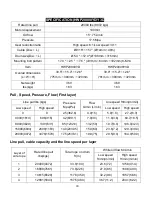
Страница 24: ... Mpa Psi Flow G min L min Line speed ft min m min Low speed High speed Low speed High speed 0 0 2 5 362 6 4 0 15 5 9 1 8 27 2 8 3 4000 1814 696 316 4 2 609 1 7 9 30 11 8 3 6 60 7 18 5 8000 3629 1391 631 8 5 1232 8 13 2 50 19 7 6 0 106 0 32 3 15000 6804 2609 1183 14 0 2030 5 15 9 60 23 6 7 2 129 3 39 4 20000 9072 3478 1578 17 5 2538 1 19 9 75 29 5 9 0 164 0 50 0 Line pull cable capacity and the lin...

Страница 25: ...36 8 15 4 12 6 935mm 390mm 320mm Net weight Ibs kg 360 163 360 163 Pull Speed Pressure Flow First layer Line pull lbs kgs Pressure Mpa Psi Flow G min L min Line speed ft min m min 0 2 5 362 6 4 0 15 5 9 1 8 4000 1814 4 2 609 1 7 9 30 11 8 3 6 8000 3629 8 5 1232 8 13 2 50 19 7 6 0 15000 6804 14 0 2030 5 15 9 60 23 6 7 2 20000 9072 17 5 2538 1 19 9 75 29 5 9 0 Line pull cable capacity and the line s...

Страница 26: ... Mpa Psi Flow G min L min Line speed ft min m min Low speed High speed Low speed High speed 0 0 2 5 362 6 4 0 15 5 9 1 8 27 2 8 3 4000 1814 696 316 4 2 609 1 7 9 30 11 8 3 6 60 7 18 5 8000 3629 1391 631 8 5 1232 8 13 2 50 19 7 6 0 106 0 32 3 15000 6804 2609 1183 14 0 2030 5 15 9 60 23 6 7 2 129 3 39 4 20000 9072 3478 1578 17 5 2538 1 19 9 75 29 5 9 0 164 0 50 0 Line pull cable capacity and the lin...

Страница 27: ...35 0 15 4 12 6 889mm 390mm 320mm Net weight Ibs kgs 360 163 360 163 Pull Speed Pressure Flow First layer Line pull lbs kgs Pressure Mpa Psi Flow G min L min Line speed ft min m min 0 2 5 362 6 4 0 15 5 9 1 8 4000 1814 4 2 609 1 7 9 30 11 8 3 6 8000 3629 8 5 1232 8 13 2 50 19 7 6 0 15000 6804 14 0 2030 5 15 9 60 23 6 7 2 20000 9072 17 5 2538 1 19 9 75 29 5 9 0 Line pull cable capacity and the line ...

Страница 28: ...mm Net weight Ibs kgs 238 108 Pull Speed Pressure Flow First layer Line pull lbs kgs Pressure Mpa Psi Flow G min L min Line speed ft min m min 0 2 5 362 6 4 0 15 5 9 1 8 4000 1814 4 2 609 1 7 9 30 11 8 3 6 8000 3629 8 5 1232 8 13 2 50 19 7 6 0 15000 6804 14 0 2030 5 15 9 60 23 6 7 2 20000 9072 17 5 2538 1 19 9 75 29 5 9 0 Line pull cable capacity and the line speed per layer Layer of wire rope Rat...

Страница 29: ... 14 8 2 5 7 6 375mm 64mm 192mm 8 M14 Overall dimensions L W H 22 2 14 2 14 0 564mm 360mm 356mm Net weight Ibs kgs 238 108 Pull Speed Pressure Flow First layer Line pull lbs kgs Pressure Mpa Psi Flow G min L min Line speed ft min m min 0 2 5 362 6 4 0 15 5 9 1 8 4000 1814 4 2 609 1 7 9 30 11 8 3 6 8000 3629 8 5 1232 8 13 2 50 19 7 6 0 15000 6804 14 0 2030 5 15 9 60 23 6 7 2 20000 9072 17 5 2538 1 1...

Отзывы: