background image


15 


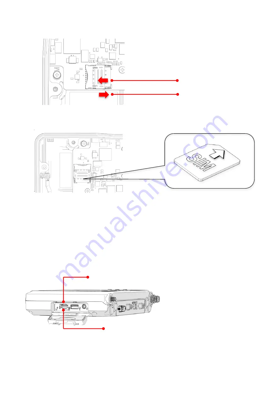
6.  Turn your SIM card to the angled corner of your SIM card to match the angled corner of 

the SIM card holder. 


7.  Insert the SIM card into the SIM card holder. 

8.  Close the cover of the SIM card holder. 

External SIM slot (SIM1) 

1.  Shut down the system properly and disconnect the device from all power sources. 

2.  Open the side cover; you can see the Micro SIM card and SD card slot. 


SIM Card Slot 

SD Card Slot 

To open the SIM card holder 

To lock the SIM card holder 


Содержание RuggVMC MT7010

Страница 1: ...MT7010 User s Manual v1 1...

Страница 2: ...ENVIRONMENT 9 I O PORTS 10 DIMENSION AND WEIGHT 11 MT7010 STANDARD 11 PACKAGE LIST 12 CHAPTER 2 HARDWARE INSTALLATION 13 INSTALLING REMOVING THE SIM CARD 13 INTERNAL SIM SLOT SIM2 13 EXTERNAL SIM SLOT...

Страница 3: ...22 485 PORT COM2 27 DIO AND CAN BUS PORT 28 CHAPTER 6 DASHON SETTING 29 DEVICE INFORMATION 30 VEHICLE STATUS 31 COMMUNICATION SETTING 32 ENABLE DISABLE MODULE 32 WWAN SETTING 33 SYSTEM STATUS SETTING...

Страница 4: ...tlet 10 Place the power cord in a way so that people will not step on it Do not place anything on top of the power cord Use a power cord that has been approved for use with the product and that it mat...

Страница 5: ...pin If your outlet does not support this kind of plug contact your electrician to replace your obsolete outlet 18 CAUTION DANGER OF EXPLOSION IF BATTERY IS INCORRECTLY RE PLACED REPLACE ONLY WITH THE...

Страница 6: ...ss B digital device pursuant to Part 15 of the FCC Rules These limits are designed to provide reasonable protection against harmful interference in a residential installation This equipment generates...

Страница 7: ...tact your local representative for ordering information This product has passed the CE test for environmental specifications Test conditions for passing included the equipment being operated within an...

Страница 8: ...ce is engineered with IP65 protection rating a wide temperature design wide input range and rich expanding interfaces that support in vehicle connectivity Hardware Specifications Item Description Proc...

Страница 9: ...rage Relative humidity 5 to 95 30 C 86 F to 60 C 140 F non condensing in accordance with MIL STD 810G CHANGE1 Method 507 6 Humidity Procedure II Aggravated Cycles Fig 507 6 7 Vibration Test Operating...

Страница 10: ...SB storage is functional simultaneously Ethernet 10 100Base T RJ45 x 1 Digital I O 2 x DI 2 x DO Digital Input DI 0 30V Digital Output 1 circuit design reserved for 2 x DO 5V 2 default setting 2 x DO...

Страница 11: ...11 Dimension and Weight MT7010 Standard Dimension 219 98 x 151 98 x 40 8mm 8 66 x 5 98 x 1 60in W x H x D Weight 1 25 kg 2 76 lbs Front View Dimension Side View Dimension...

Страница 12: ...very of the contents upon receipt MT7010 in vehicle terminal Bare wire power cable with circular power connector 2 feet DB15 male connector cable with multiple end 2 feed DB15 male connector cable no...

Страница 13: ...tion can be done via SIM slot assignment in DashON The factory default is the external SIM slot SIM1 Please see the following guidelines to install or remove the SIM card Please make sure that the dev...

Страница 14: ...4 Once the service cover is removed you can see the Micro SIM card slot 5 To release the SIM card holder slightly lift the front edge of the cover on the card holder and slide it backwards Open the co...

Страница 15: ...card into the SIM card holder 8 Close the cover of the SIM card holder External SIM slot SIM1 1 Shut down the system properly and disconnect the device from all power sources 2 Open the side cover yo...

Страница 16: ...16 3 Insert your SIM card Make sure the angled corner of the card is positioned correctly...

Страница 17: ...pports a standard VESA version MIS D 75 C 75mm distance quadrate order M5 thread deepness 6mm through the four drill holes on the back side of the device Notes To prevent any damage or injury make sur...

Страница 18: ...ows a wide range of DC power input from 9 36V via a 5 pin M12 A code power cord There are two options to start up the MT7010 via car power cable or external power adapter The wire definition Wire Colo...

Страница 19: ...supply Please follow the wire definition to connect to your power source 2 Plug the power code into the power connector on the top of the arrow mark 3 Twist the nut to lock the power connector to the...

Страница 20: ...ower source isn t controlled by AAC Ignition signal Please short red V and white ACC Ignition wires Make sure that all the power supplies are disconnected when you plug the power cord into the power c...

Страница 21: ...t possible failed hardware components causing specific symptoms There are two status indicators in the front panel Refer to the description below LED Status Description PWR Blink Green Power up PWR Bl...

Страница 22: ...volume lower Press the button to increase the volume Press the button to decrease the volume Auto Brightness Adjustment When you use MT7010 you may well encounter different lighting conditions that ma...

Страница 23: ...es default commands for five programmable buttons You can configure the programmable buttons via DashON to different commands or keyboard shortcuts to better fit your work style Power Management In ad...

Страница 24: ...24 Chapter 5 Jumpers and Connectors Bottom View Power Input Connector GPS Antenna Connector SMA Jack RS 232 with PWR COM1 LAN DIO CAN bus RS 232 422 485 USB 2 0 conversion COM2...

Страница 25: ...s a reference for the pin assignments of the various ports available on the MT7010 Power Connector Pin Signal 1 DC 2 N A 3 GND 4 N A 5 ACC Ignition Note Please refer to section 1 in Chapter 4 for conn...

Страница 26: ...t 2 RXD Receive data input 3 TXD Transmit data output 4 DTR Data terminal ready output 5 GND Signal power ground 6 DSR Data set ready input 7 RTS Request to send output 8 CTS Clear to send input 9 RI...

Страница 27: ...5 TX 4 RS 232 TX 5 GND 6 RS 422 TX 7 RS 422 RX 8 RS 485 TX 9 USB 5V 10 RS 232 RX 11 GND 12 USB DP 13 USB DM 14 USB 5V 15 NC We provide Y cable with DB15 male connector which is the RS232 422 485 and U...

Страница 28: ...6 CAN_L 7 N A 8 N A 9 CARD POWER 10 GND 11 N A 12 DIO_OUT1 5V 10mA 13 DIO_IN1 5V 100mA 14 DIO_IN2 5V 100mA 15 DIO_OUT2 5V 10mA We provide the DB15 male connector to multiple pins without termination...

Страница 29: ...n 2 Vehicle Status This section is to demo how to read the vehicle information such as vehicle battery voltage fuel speed and so on while connecting with vehicle SAE J1939 We use the simulator to run...

Страница 30: ...30 Device Information Click on the Device Information icon In device information you can see the PCBA version DashON utility version and system model name...

Страница 31: ...Vehicle Status Vehicle status shows some vehicle information from the simulator The related AT command is available upon request Please contact local sales representatives or login to the support webs...

Страница 32: ...to enable disable Wi Fi WWAN Bluetooth via DashON utility Please click on the Communication Setting Enable Disable Module Item 1 Click on the switch bar to Enable Disable Wi Fi function Item 2 Click o...

Страница 33: ...the detailed setting You can set the two major features including WWAN RF on off and SIM slot selection 1 Module RF Enable Disable to enable or disable the WWAN RF transmission A message will then po...

Страница 34: ...tus Setting This section is to set and read the system status It covers power management internal backup battery IO configuration wake up event and so on Power Management Setup Please click on the Pow...

Страница 35: ...Input Voltage Setting Click on the to the input voltage selection You can select the power input voltage either 9 36V or 12V or 24V If 9 36V is selected it means the system can be powered on while the...

Страница 36: ...36 If 12V or 24V is selected you can also select the startup and shut down voltage setting...

Страница 37: ...37...

Страница 38: ...38 If the above selection items do not meet your demand please contact local sales representatives...

Страница 39: ...ACC is on for a specified period of time Enabled power off delay function lets the device remain on until the ACC is off for a specified period of time Power On Delay Switch the to click on the and yo...

Страница 40: ...40 Power Off Delay Same as power on delay setting process you can also set the power off delay Delay time can be set at 10sec 30sec 1min 5min 10min 15min 30min 60min 6hr...

Страница 41: ...ect with barcode scanner or other equipment The maximum current is up to 5V 600mA 12V 300mA If you don t need the power output just select 0V output to avoid the equipment damage Please note if system...

Страница 42: ...the brightness is auto adjusted along with the changes of environmental light You can also manually change the display brightness via programmable buttons or the bar adjustment in DashON For programm...

Страница 43: ...43 Double click on the DashON icon and then click on the 4th icon System Status Setting Click on the Watchdog Timer...

Страница 44: ...etting Turn on the watchdog switch If you d like to test if watchdog timer is enabled and working please click on the simulation icon The simulation is to simulate the system on hang and reboot it aft...

Страница 45: ...45 Programmable Button Programmable buttons can be set to different functions per user s definition...

Страница 46: ...ct which function key button you want to set and then click the to select the function from the list User can also define the keystrokes for function keys by selecting the User Defined Command from th...

Страница 47: ...t in DashON provides both setting and information and also links to the Google map locations for demo applications You can also use the general freeware GPS viewer to set GPS setting Click on the Loca...

Страница 48: ...48 Enable Disable GPS Receiver The default GPS receiver is enabled in MT7010 If you want to disable the receiver switch Module RF to...

Отзывы: