


7
ASSEMBLY INSTRUCTIONS:
1.
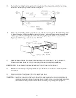
Mark the location for the rear hinge. This location should be immediately behind a truck cross
member, approximately 32" behind the center of the rear axle on single axle trucks. Refer to Figure 1
for the specific hoist model you are installing.
2.
Cut a notch in each truck chassis frame rail as illustrated in Figure 2.
3.
Position the rear hinge angle in the notch cut in Step 2. The rear hinge angle is 37 3/16" wide and
should be centered side to side in the notch as illustrated in Figure 3. Weld the rear hinge angle to
each of the truck chassis frame rails.
NOTE:
This hinge assembly is designed for a truck longsill spacing of 34" and is not recommended
for any other width.
4.
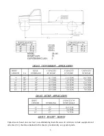
Locate the hoist on the truck frame making sure to center the hoist right and left and to square
the hoist with the truck frame. The LR-416, LR-165, and LR-25 are designed to rest on the
truck frame as shown in their respective Figure 1. A portion of the hoist extends below the
truck frame level; therefore, the hoist may be moved slightly forward to avoid truck cross
members. The distance between the rear hinge center and saddle center (Figure 1) is referred
to as the "M" dimension. In Table A, the "M" dump angles are tabulated.
NOTE:
Moving the hoist along the truck frame will affect the hoist's performance. A forward
movement will reduce the dump angle and increase capacity, while a rearward movement will
increase dump angle and decrease capacity.
Содержание 03 3018
Страница 11: ...10 ...


