Chapter 4 INSTALLAION
Глава 4 УСТАНОВКА
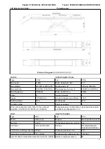
Picture / Рисунок 18
(
rolling jack dimension / габариты траверсы
)
LINE CONNECTION
ПОДКЛЮЧЕНИЕ ПИТАНИЯ
Connect the electrical circuit and oil pipe according to
the electrical diagram and oil pip connection diagram.
Подключите электричество и гидравлику в
соответствие с электро- и гидравлической схемами
To avoid the unexpected lift closure due to
mechanical safety device release insert
wooden pieces in the inner part of the base
frame.
Во избежание неожиданного срабатывания
механизма фиксации платформ подъёмника,
заблокируйте фиксатор при помощи деревянного
бруска.
Pay attention not to work under the lift until the
hydraulic system has not been completely filled with
hydraulic oil.
Не работайте под подъёмником до тех пор пока
гидравлическая система не будет наполнена
маслом.
To insert the lift into the recess, sling the lift as
described and pay attention not to damage the
hoses and electrical cables.
При установке платформ в ниши, обратите особое
внимание на сохранение целостности проводов и
шлангов.
Before placing the pneumatic and hydraulic hoses
to the control unit, stick adhesive tape on the pipe
fittings in order to protect the hoses from dust and
impurities which could damage the hydraulic system.
Перед подключением пневмо- и гидрошлангов в
стойку управления, заклейте фиттинги изолентой,
для исключения попадания посторонних частиц
и/или элементов в гидравлическую систему.
Perform electrical, oil pipes and air pipes connections,
carefully follow the relevant numbers. Regarding the
proper connections is necessary to make the car lift
perfectly working.
Подключайте электро-, гидро- и пневмошланги
соблюдая нумерацию. Соблюдение данного
требования необходимо для корректной работы
подъёмника.
Skilled personnel only are allowed to
perform the operations shown below.
Только опытный персонал имеет право
выполнять нижеописанные операции.
-Open the control box front cover.
- Откройте переднюю крышку стойки управления
-Connection of power supply: the connection wires (BVR-
4*2.5mm2) for power supply are connected to terminals
1#, 2#, 3#, The ground wire is connected under the bolt
marked ground.
- Подключение электропитания: соединительные
провода (BVR-4*2.5mm2) источника питания
присоединяются к клеммам 1#, 2#, 3#. Провод
заземления подключается болтом.
-The electric panel is arranged by the manufacturer for
operating at 400V three-phase, therefore if you wish the
lift to be operated at 230V three-phase, change
the connection on the transformer and motor.
- Электрическая схема подключения разработанная
производителем предполагает наличие напряжения
380В, 3-ёх фазное (рис.19), поэтому если вам
требуется подключить подъёмник к источнику 220В,
вам следует изменить подключение трансформатора
и мотора (рис.20).
Picture / Рисунок 19
Picture / Рисунок 20
17
Содержание RLS-G 3.5T
Страница 29: ...9 ACCESSORY 9 9 2 Oil pipe connection diagram 9 2 29...
Страница 31: ...9 3 Lift explosion diagram 9 3 31...


