2
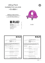
B-ABA
Before initial usage of the RUD lifting point
B-ABA, please read carefully the safety
instructions. Make sure that you have un-
derstood all subjected matters.
Non-observance can lead to serious per-
sonal injuries and material damage and
eliminates warranty.
1 Safety instructions
ATTENTION
Wrong assembled or damaged lifting
points B-ABA as well as improper use
can lead to injuries of persons and
damage of objects when load drops.
Please inspect all lifting points before each
use.
• RUD lifting points B-ABA must only be used by in-
structed and competent persons considering BGR
500 (DGUV-rules 100-500) and outside Germany
noticing the country specific statutory regulations.
2 Intended use of the B-ABA
RUD lifting points B-ABA must only be used for the
assembly at the load or at lifting means.
They are intended to be hinged into lifting means.
RUD lifting points B-ABA can also be used as lashing
points to attach lashing means.
Loading from any side is permitted.
RUD lifting points B-ABA must only be used in the
hereby described operation purpose.
3 Assembly- and instruction manual
3.1 General information
• Capability of temperature usage:
When used at higher temperatures the working
load limit (WLL) of the lifting point must be redu-
ced as follows:
-
-40°C up to 200°C
no reduction
-
200°C up to 300°C
minus 10 %
-
300°C up to 400°C
minus 25 %
Temperatures exceeding 400°C are prohibited!
• RUD lifting points B-ABA must not be used with
aggressive chemicals such as acids, alkaline so-
lutions and their vapours.
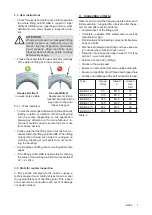
• Please mark mounting position of lifting point with
a coloured contrast paint for better visibility.
3.2 Hints for the assembly
Basically essential:
• The material construction to which the lifting point
will be attached should be of adequate strength to
withstand forces during lifting without deformation.
The German testing authority BG/DGUV, recom-
mends the following minimum for bolt lengths:
1x M in steel (minimum quality S235JR[1.0037])
1.25x M in cast iron (however when castings of
lower strength [<200 MPa] are used the
thread engagement has to be at least 1,5xd)
2x M in aluminum alloys
2.5x M in light metals of low strength
(M = thread size, e.g. M20)
• The position of the lifting points must be carried
out in such a way that unintended movement like
turning or flipping will be avoided:
•
For single leg lifts:
the lifting point should be
vertically above the centre of gravity of the load.
•
For two leg lifts:
the lifting points must be
equidistant to/or above the centre of gravity
of the load.
•
For three and four leg lifts.
the lifting points
should be arranged symmetrical around the
centre of gravity, in the same plane if possible.
• Symmetry of loading:
Determine the necessary WLL of each lifting point
for a symmetrical or an unsymmetrical load by
using the following physical calculation formula:
Number of load bearing strands:
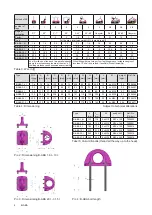
Table 1: Load bearing strands (compare to table 3)
• RUD lifting points B-ABA must be installed
by using the supplied ICE-bolts.
If needed, Vario-ICE-bolts can be ordered on re-
quest (compare chart 5 / pic. 4).
• A plane bolt-on surface must be ensured resp.
provided. Blind holes must be drilled deep enough,
that the supporting area of the B-ABA fits properly.
Tighten bolts with required torque value (see table
2).
• For a single use hand tightening with a spanner is
sufficiant. Bolt supporting area must sitproper on
bolt-on surface.
• Check finally the correct assembly (see chapter 4,
Inspection criteria).
symmetric
unsymmetric
two leg
2
1
three / four leg
3
1
W
LL
= necessary WLL (kg) of lifting point /
single strand (kg)
G
= weight of load (kg)
n = number of load bearing strands
ß
= Inclination angle of single strand
W
LL
=
G
n x cos ß


