

Copyright © 2013 Ruckus Wireless, Inc.
Published October 2013, Part Number 800-70507-001 Rev C
M
OU
NTING TEMPLA
TE
mm
3
Press <Enter> to initiate the connection. When a security
alert dialog box appears, click
OK/Yes
to proceed.
4
When the
Ruckus Wireless Admin
login page appears, enter
the following:
•
Username
: super
•
Password
: sp-admin
5
Click
Login
.
S
TEP
4: C
USTOMIZE
THE
W
IRELESS
S
ETTINGS
1
On the Web interface menu, click
Configuration
>
Wire-
less [2.4G/5G]
. The Configure :: Wireless :: Common
options appear.
2
Verify that the following options are active:
•
Channel
: SmartSelect
•
Country Code
: If you are not located in the United
States, select your current country.
3
Click
Update Settings
if you made any changes.
4
Click any of the eight “Wireless #” tabs at the top of the
page.
5
In
Wireless Availability
, click
Enabled
.
6
Delete the text in the
SSID
field, and then type a name for
your network that will help your users identify the AP in their
wireless network connection application.
7
Click
Update Settings
to save your changes.
8
Repeat Steps 4-7 for each Wireless # interface that you want
to enable.
9
Click
Logout
to exit the Web interface.
10
Disconnect the AP from the computer and from the current
power source, and then restore your computer to its original
network connection configuration.
S
TEP
5: P
LACE
THE
AP
IN
Y
OUR
S
ITE
1
Move the AP to its permanent location (accessible to both
AC power and network connection).
2
Use an Ethernet cable to connect the 10/100/1000 port of
the AP to your network.
3
Connect the AC power adapter (or PoE power supply) to the
AP, then to a convenient power source.
4
Verify that the 10/100/1000 port LED is lit.
S
TEP
6: V
ERIFY
THE
I
NSTALLATION
1
Using any wireless-enabled computer or mobile device,
search for and select the wireless network you previously
configured.
2
If you can connect, open a browser and link to any public
Web site.
Congratulations!
Your wireless network is active and ready
for use. If you need to configure advanced wireless settings,
such as enabling security, see the ZoneFlex AP User Guide.
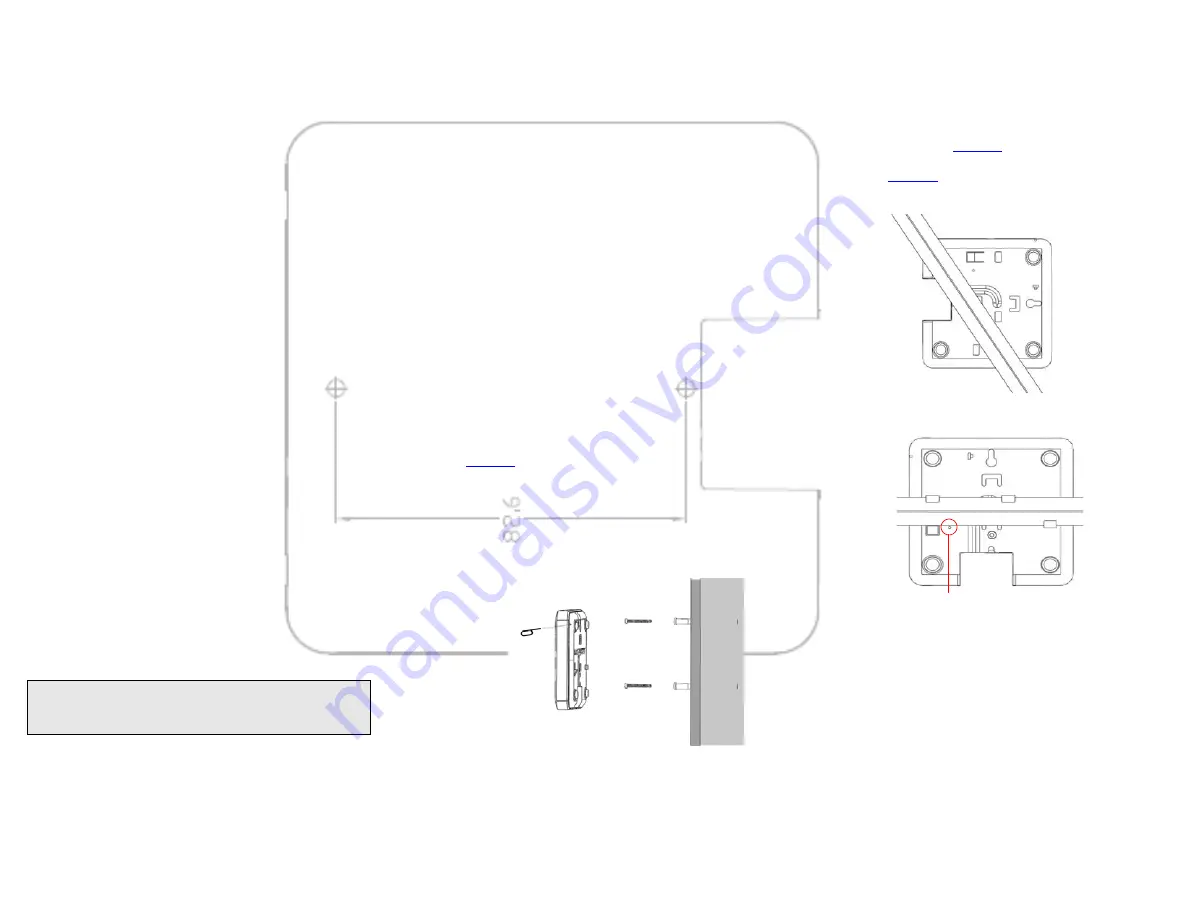
(O
PTIONAL
) M
OUNTING
I
NSTRUCTIONS
The ZoneFlex R300 can be mounted to a wall, ceiling or to a
T-bar using the supplied mounting screws or the T-bar clips
built into the bottom of the AP enclosure.
Mounting to a Flat Surface
1
Use this
Quick Start Guide
template to mark the locations
for screw holes on the mounting surface. Use a 5mm drill bit
to drill approximately 25mm into the mounting surface.
2
Insert the anchors and mounting screws into the mounting
surface, leaving approximately 1/4” (6 mm) of the screw
heads protruding for the AP enclosure.
The screws should be approximately 3.25” (82.6mm) apart
per the template.
3
Insert the unit removal pin into the hole on the side of the
AP (
), to release the locking mechanism.
Figure 1. Insert the unit removal pin into the pinhole
4
Place the AP onto the mounting screws so that the screw
heads enter the mounting holes on the AP enclosure, and
push the AP (to the left or down depending on orientation)
to lock in place.
5
Remove the unit removal pin to release the lock mechanism
and secure the AP.
6
To unmount, insert the unit removal pin into the hole on the
side of the AP to unlock, then push the AP (to the right or up,
depending on orientation) to release the AP enclosure from
the mounting screws.
Mounting to a T-Bar
1
Orient the AP so that the T-bar is positioned between the T-
bar clips as shown in
, then rotate the AP until the
third T-bar clip catches the T-bar and the latch locks the T-bar
in place (
Figure 2.
Figure 3.
2
For added physical security, use a Torx screwdriver to insert
the security screw into the hole shown in Figure 3.
3
To remove the unit, first remove the security screw, then
depress the latch while rotating the AP so that the T-bar clips
disengage the T-bar.
F
OR
M
ORE
I
NFORMATION
For information on how to configure the AP from the Web
interface, refer to the
Ruckus Wireless ZoneFlex Access Point
User Guide
or the Online Help, available from within the
Web interface.
NOTE:
If you will be using PoE, you will need a Cat 5e (or
better) Ethernet cable to connect the AP to the PoE injec-
tor or switch.
Hold unit removal pin
in while mounting
Security screw hole


