background image

T504 AP Installation Guide, 800-71032-001 Rev D 

Installing the T504 

Deploying the T504 

27 


6


Select 

IP address automatically

, and then configure the IP address settings with the values 

listed in 

Table 6

. For a sample configuration, refer to 

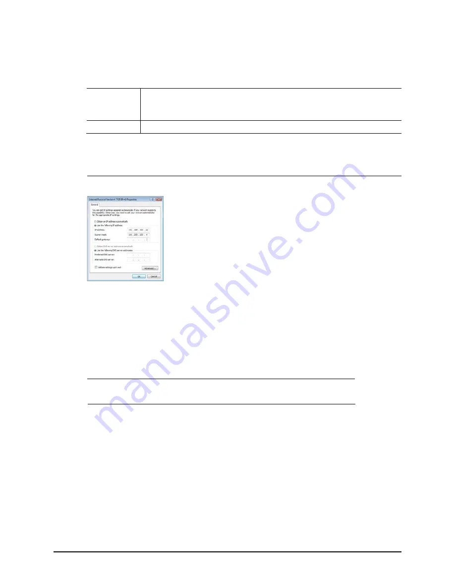
Figure 8

Table 6.  Configure your computer’s IP address settings 


IP address 

Use the following IP address. 

(Avoid 192.168.100.1, which is the default 

IP address assigned to the CM, and 192.168.100.2, which is the default IP address 
assigned to the AP.) 

Subnet mask 

255.255.255.0


Note 1: 

The administrative computer needs to be able to connect with 192.168.100.2, the IP 

address for the AP. The administrative computer also needs to connect with the CM, which has 
probably been assigned a new IP address by the network DHCP server. 

Note 2: 

You can leave the 

Default Gateway 

and 

DNS server 

fields blank. 


Figure 8.  Sample configuration in the Internet Protocol Version 4 (TCP/IPv4) Properties dialog 


7


Click 

OK 

to save your changes and close the 

TCP/IP Properties 

dialog. 

8


Click 

OK 

again to close the 

Local Area Connection Properties 

dialog. 

Continue with 

Operating the CM

. 

Operating the CM 

In addition to the T504 AP command line interface (CLI) and Web interface, the CM part of the T504 
also has Web and CLI interfaces. With these interfaces, you can operate the CM part. Refer to the 
following sections: 


NOTE  

The cable modem and access point each has its own independent firmware load that is 

updated independently. 


o


Logging Into the CM Web Interface


o


Viewing the Software Status


o


Viewing the Connection Status


o


Configuring the Downstream Frequency


o


Administering Cable Modem Passwords


Logging Into the CM Web Interface 

The CM command line interface is similar to the AP CLI, and is used for CM-specific operations. You 
can perform most CM operating tasks from the CM Web interface. Log into the CM Web interface 
as follows: 

1


Collect required equipment and information: 

Содержание ZoneFlex 901-T504-US31

Страница 1: ...ZoneFlexTM T504 Access Point Installation Guide Applies to 901 T504 US31 and 901 T504 WW31 Part Number 800 71032 001 Rev D Published October 2016 www ruckuswireless com...

Страница 2: ...2 T504 AP Installation Guide 800 71032 001 Rev D...

Страница 3: ...ION AND ALL INFORMATION CONTAINED HEREIN MATERIAL IS PROVIDED FOR GENERAL INFORMATION PURPOSES ONLY RUCKUS AND ITS LICENSORS MAKE NO WARRANTY OF ANY KIND EXPRESS OR IMPLIED WITH REGARD TO THE MATERIAL...

Страница 4: ...4 T504 AP Installation Guide 800 71032 001 Rev D...

Страница 5: ...unding the T504 22 Installing the Cable Power Tap 23 Powering the T504 with POC 24 Checking the T504 Signal Level with an RF Power Meter Optional 25 Configuring the T504 for the First Time Optional 26...

Страница 6: ...x C Replacing the F Connector Adapter Appendix D Rebooting and Resetting the T504 Rebooting and Resetting the AP and CM 51 Using the Reset Button Inside the AP 51 Remotely Rebooting and Factory Resett...

Страница 7: ...k Topics covered in this guide include basic configuration operation and mounting The rest of this document refers to the strand mount access point with integrated cable modem as the T504 This guide i...

Страница 8: ...on Guide The T504 installation is completed with four main steps Each step includes some substeps Figure 2 shows the main steps and Table 1 includes the substeps Figure 2 Adding a T504 to an existing...

Страница 9: ...rmation o Unpacking the T504 o Finding the AP and CM MAC Addresses o Connectors and Ground Point o LEDs and Reset Button Diagnostic Ethernet Port o Dimensions o Deploying the T504 o Verifying CM and A...

Страница 10: ...led information on how to configure the functions of the unit The User Guide is available for download on the Ruckus Wireless Support Web site at http support ruckuswireless com documents o Release No...

Страница 11: ...lation Guide 800 71032 001 Rev D 11 Planning the T504 Installation 2 Before installing the T504 plan the T504 installation In this chapter o T504 Omni Antenna Coverage o Powering Options o Performing...

Страница 12: ...atest reach and throughput to a wide coverage area and provide the greatest distance between APs in a connecting device See Figure 3 for internal antenna coverage patterns and see Figure 4 for a typic...

Страница 13: ...ing the radio higher off of the ground with the AP oriented so that the dome is tilted down For recommended orientation examples refer to T504 Omni Antenna Coverage o Physical environment Clear or ope...

Страница 14: ...T504 AP Installation Guide 800 71032 001 Rev D Planning the T504 Installation Performing a Site Survey 14...

Страница 15: ...ommends that you first complete the procedures described in Planning the T504 Installation In this chapter o Safety Information o Unpacking the T504 o AP and CM MAC Addresses Connectors and Ground Poi...

Страница 16: ...stallation of this equipment must comply with local and national electrical codes WARNING Ruckus Wireless strongly recommends that you wear eye protection before mounting the AP CAUTION Make sure that...

Страница 17: ...sales representative NOTE Appendix A Ruckus Wireless Factory and Customer Supplied Parts includes illustrations and descriptions of these and other factory orderable and customer supplied parts Packa...

Страница 18: ...ground point screw Figure 5 T504 MAC address label F type connector and ground point Table 2 Connectors and ground point on the T504 No Label Description 1 MAC Address Label location Labels include s...

Страница 19: ...then blinks as upstream power is increased ranged and then solid when upstream ranging is complete Also blinks during CM boot when power is applied 4 ONLINE o Off until CM DS and CM US are solid ON th...

Страница 20: ...ng bootup 2 CM DS LED blinks while finding CM downstream link then solid once complete 3 CM US LED blinks while finding CM upstream link then solid once complete 4 Online LED blinks while getting new...

Страница 21: ...nal o Configuring the T504 for the First Time Optional Mounting the T504 To mount the T504 assembly on a cable strand you need to secure the cable clamps that are attached to the strand interface to t...

Страница 22: ...he cable strand is not earth grounded then continue with the following 1 The color coding of ground wires varies by region Before completing this step check your local wiring standards for guidance 2...

Страница 23: ...ble Figure 7 shows a typical cable power tap and connection to the CM using an RG6 quad shield cable Table 4 describes the elements in Figure 7 NOTE If the F connector on the T504 is damaged then refe...

Страница 24: ...n the T504 as shown in Figure 5 3 Finger tighten the coaxial cable connector and then tighten to 3 4N m 30in lbs 4 Plug the power jumper back into the power tap to restore AC power out of the power ta...

Страница 25: ...l cable connector signal level specifications Downstream Upstream 12dBmV to 16dBmV 64 QAM or 12dBmV to 16dBmV 256 QAM TDMA 1xUpstream o Pmin to 57dBmV 32 QAM 64 QAM o Pmin to 58dBmV 8 QAM 16 QAM o Pmi...

Страница 26: ...dress settings 1 Collect required equipment and information o An administrative computer notebook computer with an Ethernet port and a wireless card installed o A Web browser such as Google Chrome Moz...

Страница 27: ...nfiguration in the Internet Protocol Version 4 TCP IPv4 Properties dialog 7 Click OK to save your changes and close the TCP IP Properties dialog 8 Click OK again to close the Local Area Connection Pro...

Страница 28: ...Web browser window 5 In the address or location bar enter the IP address that is assigned to the cable modem for instance 192 168 100 1 OR DHCP assigned CM IP address The cable modem Web interface dis...

Страница 29: ...ble 8 Status table Item Description System Up Time Indicates the time that has elapsed since the cable modem was last rebooted Network Access Indicates whether or not the cable modem is connected to t...

Страница 30: ...o the CM Web Interface 2 Click Configure in the left sidebar The CM Web interface displays the Configure Status page See Figure 12 Figure 12 Configure Status page 3 In the Configure DS Frequency text...

Страница 31: ...ry defaults as follows o Select the Restore Factory Defaults Yes button to reset all the CM parameters to the factory default settings after the next reboot o Select the Restore Factory Defaults No bu...

Страница 32: ...wdriver with sockets and bits o 100 silicon sealant 2 If you have connected an administrative computer to the Ethernet cable to the T504 Ethernet port then disconnect the cable 3 Wipe any dirt or othe...

Страница 33: ...find the CM s MAC address on the T504 you can retrieve it via the CMTS using the AP and CM command line interfaces o Retrieving the CM s MAC Address using the CM CLI o Retrieving the CM s MAC Address...

Страница 34: ...to the AP using Telnet or SSH with the following logon details o User names super o Password sp admin 5 When command prompt appears enter the following command get cm supportinfo Basic Info MAC Addres...

Страница 35: ...integer spaced by 6MHz first from 93MHz to 999MHz 152 channels 4 Scans the harmonically related carrier HRC channels which moves the channels 1 25MHz off the standard frequencies so the video carrier...

Страница 36: ...T504 AP Installation Guide 800 71032 001 Rev D Operating and Troubleshooting the T504 How Radio Frequency Scanning Works 36...

Страница 37: ...ed networks anyone with a compatible wireless adapter can receive wireless data transmissions from your network Toprevent unauthorizedusers from enteringyourwireless network and accessing your compute...

Страница 38: ...T504 AP Installation Guide 800 71032 001 Rev D 38 What to Do Next Reading Related Documentation...

Страница 39: ...tory and Customer Supplied Parts Table 9 Factory supplied and customer supplied parts Part Ruckus Wireless P N T504 Kit or Customer Supplied Notes 1m lugged earth ground wire T504 kit Cable power tap...

Страница 40: ...T504 AP Installation Guide 800 71032 001 Rev D 40...

Страница 41: ...T504 AP Installation Guide 800 71032 001 Rev D 41 Appendix B T504 Mounting Dimensions and Weight Dimensions Figure 14 T504 length all dimensions in millimeters and inches B...

Страница 42: ...T504 AP Installation Guide 800 71032 001 Rev D 42 Dimensions Figure 15 T504 height and width all dimensions in millimeters and inches...

Страница 43: ...T504 AP Installation Guide 800 71032 001 Rev D Weight 43 Weight The T504 weighs 9 5 pounds For other specifications refer to the Ruckus Wireless data sheet...

Страница 44: ...T504 AP Installation Guide 800 71032 001 Rev D Weight 44...

Страница 45: ...ts o Wire cutters o 100 silicon sealant 2 Using a 7 16 wrench unscrew and remove the stinger screw in access plug 1 in Figure 16 next to the stinger F connector 2 in Figure 16 Figure 16 F connector an...

Страница 46: ...Phillips retaining screw head 3 and 1 in Figure 18 Figure 18 F connector replacement detail 7 Using a torque screwdriver or wrench tighten the stinger adapter 4 in Figure 18 to 1 7N m or 15in lbs as d...

Страница 47: ...and or rebooting the AP and CM disrupts all wireless network communications through this device There are different ways to reboot or reset the AP and CM parts of the T504 o Using the Reset Button In...

Страница 48: ...is procedure you must first obtain the related MIBs from Ruckus Wireless Contact your authorized Ruckus Wireless sales representative or Ruckus Wireless Support Visit http support ruckuswireless com c...

Страница 49: ...contact information login required 1 Connect the administrative computer to the same network as the T504 2 Start your MIB browser 3 Load the Ruckus Wireless MIBs onto the MIB browser 4 In the MIB bro...

Страница 50: ...T504 AP Installation Guide 800 71032 001 Rev D 50...

Страница 51: ...T504 AP Installation Guide 800 71032 001 Rev D 51...

Страница 52: ...Copyright 2006 2016 Ruckus Wireless Inc 350 West Java Dr Sunnyvale CA 94089 USA www ruckuswireless com...

Отзывы: