

Copyright © 2012 Ruckus Wireless, Inc.
Published June 2012, Part Number 800-70393-001
6
Delete the text in the
SSID
field, and then type a name
for your network that will help your users identify the AP
in their wireless network connection application.
7
Click
Update Settings
to save your changes.
8
Repeat Steps 4-7 for each Wireless # interface that you
want to enable.
9
Click
Logout
to exit the Web interface.
10
Disconnect the AP from the computer and from the cur-
rent power source, and then restore your computer to its
original network connection configuration.
S
TEP
5: P
LACE
THE
AP
IN
Y
OUR
S
ITE
1
Move the AP to its permanent location (accessible to both
AC power and network connection).
2
Use an Ethernet cable to connect the 10/100/1000 port
of the AP to your network.
3
Connect the AC power adapter to the AP, then to a con-
venient power source.
4
Verify that the 10/100/1000 port LED is lit.
After a short pause to re-establish the Internet connection,
you can test the AP.
S
TEP
6: V
ERIFY
THE
I
NSTALLATION
1
Using any wireless-enabled computer or mobile device,
search for and select the wireless network you previously
configured.
2
If you can connect, open a browser and link to any public
Web site.
Congratulations!
Your wireless network is active and ready
for use. If you need to configure advanced wireless settings,
such as enabling security, see the AP User Guide.
(O
PTIONAL
) M
OUNTING
I
NSTRUCTIONS
The ZoneFlex 7351-U can be mounted to a wall or ceiling
using an optional mounting bracket or book/photo mount
stand (mounting accessories sold separately).
ZoneFlex 7351-U Accessory Kit part number: 902-0104-0000.
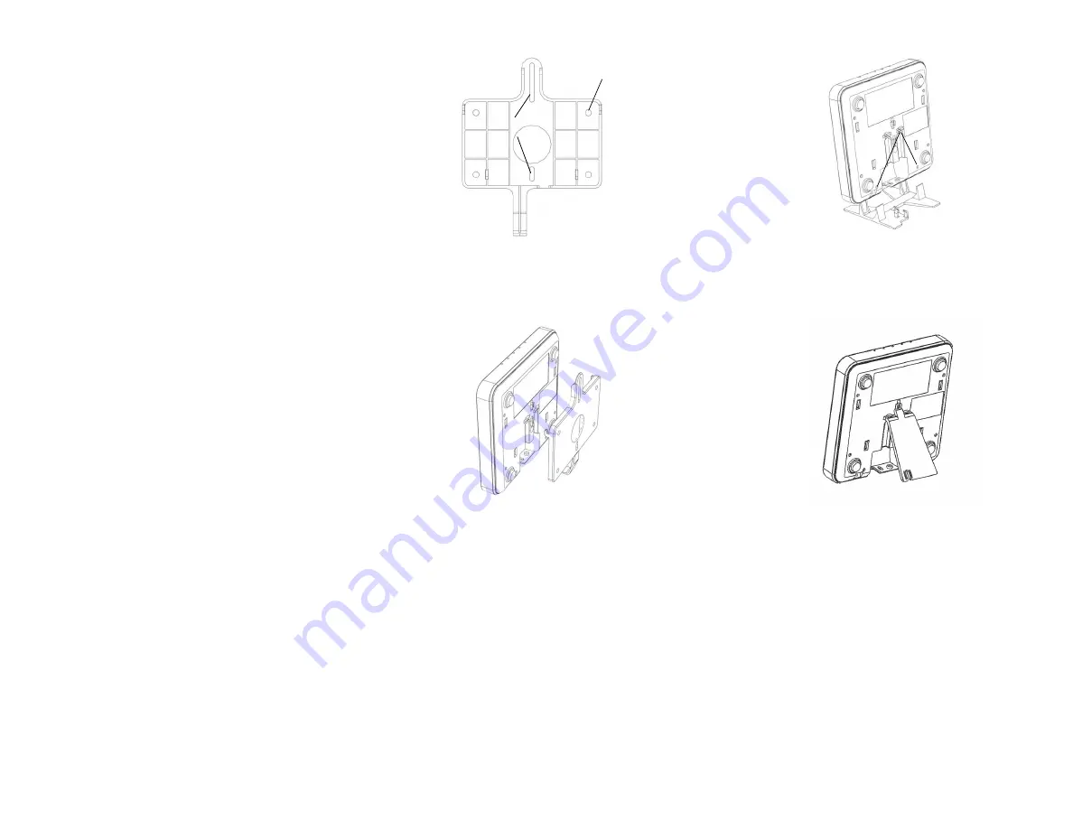
Mounting to a Flat Surface
1
Affix the mounting bracket to the mounting surface using
the mounting holes or slots (see Figure 1).
Figure 1.
2
Slide the ZoneFlex 7351-U onto the mounting bracket so
that the bracket hooks engage the AP chassis (see Figure
2).
Figure 2.
3
Lock the AP to the bracket using the supplied Torx screw.
You will need a T10 security Torx bit.
Book Mount
1
Slide the book mount stand onto the AP so that the stand
tabs enter the dimples on the AP chassis (see Figure 3).
Figure 3.
Photo Mount
1
Snap the photo mount stand into the slot on the AP chassis
as shown (Figure 4).
Figure 4.
F
OR
M
ORE
I
NFORMATION
You can now use the wireless network to log into the AP’s
Web interface. Use the Web interface to review and fine-
tune a wide range of AP settings. For information on how to
configure the AP from the Web interface, refer to the
Ruckus
Wireless ZoneFlex Access Point User Guide
or the Online
Help, available from within the Web interface.
Mounting holes
Mounting slots
Dimples


