


RTD Embedded Technologies, Inc.
|
www.rtd.com
55
DMx820 User’s Manual
7
6
5
4
3
2
1
0
Px_7
Px_6
Px_5
Px_4
Px_3
Px_2
Px_1
Px_0
R,+0
R,+0
R,+0
R,+0
R,+0
R,+0
R,+0
R,+0
Field
Description
Px_[15:0]
Captured Value. Bit definitions are:
‘0’ = Input was ‘0’ at last interrupt.
‘1’ = Input was ‘1’ at last interrupt.
6.3.7
D
UAL
I
NCREMENTAL
E
NCODER N
Each Incremental Encoder block provides two encoder channels with 16 bit counters. These two channels can be linked into a single 32
counter.
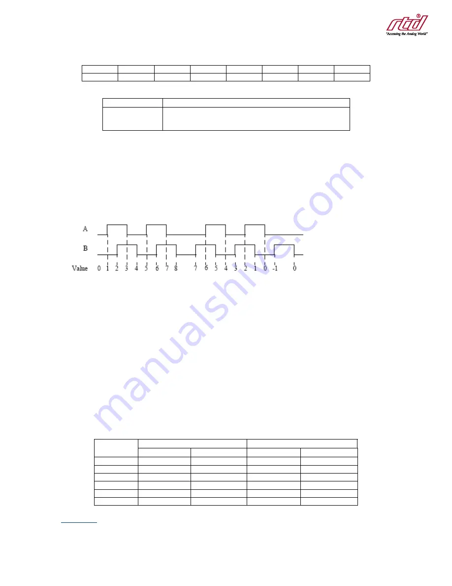
An Incremental Encoder is used to detect the relative position of a shaft or linear actuator. A typical implementation is a slotted wheel with two
optical sensors positioned such that when one sensor is positioned over a slot, the other is positioned between slots. The output of the optical
sensors is shown in Figure 12
, with one sensor named “A,” and the other named “B.” At every edge of the “A” or “B” input, the counter either
increments or decrements. The direction can be interpreted from the state of the signals, i.e. which signal leads.
Figure 12: Incremental Encoder Signals
The encoders include a “Phase Filter” that prevents the counter from counting on certain transitions. This allows the encode
rs to count pulses,
and other specialized applications.
Encoder inputs can be configured as single ended or pseudo-differential. In pseudo-
differential mode, the “+” and “
-
“ inputs must be the
inverse of each other in order for the encoder to see a change.
Digital filtering can be selected. With digital filtering, a transition on a line is only considered valid if it remains constant for four clock cycles.
The clock can be selected.
Separate interrupts are generated for positive and negative rollover. Positive rollover occurs when the counter is at its maximum value, and
receives a signal to count up. Negative rollover occurs when the counter is at 0, and receives a signal to count down. Because separate
interrupts are generated, the counter can be easily expanded in software.
The Incremental Encoder inputs are show in Table 11 below.
Table 11: Incremental Encoder Inputs
Pin
Encoder 0
Encoder 1
Channel A
Channel B
Channel A
Channel B
A+
Port0[0]
Port0[8]
Port1[0]
Port1[8]
A-
Port0[1]
Port0[9]
Port1[1]
Port1[9]
B+
Port0[2]
Port0[10]
Port1[2]
Port1[10]
B-
Port0[3]
Port0[11]
Port1[3]
Port1[11]
Index +
Port0[4]
Port0[12]
Port1[4]
Port1[12]
Index -
Port0[5]
Port0[13]
Port1[5]
Port1[13]
INCENCn_ID
ID register to identify this block.


