RS PRO SLM 1353M Скачать руководство пользователя страница 28


Integrating Sound Level Meter / EN


08/15/16 Version No. 01 
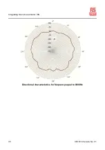
26


6. Press 

 button to store the preset start date and time, and exit this mode, the “

” 

and “ ”symbols will flash until the start time is reach. 

7. When the preset start time is reached, the data starts recording automatically, the 

start symbol “

”, will stop flashing and “ REC ” symbol will flash, the elapsed 

measurement time is displayed.  

8. During measurement, press 

 button can be used to pause and resume the 

measurement. 

During pause the pause symbol “ ” is shown and the “ REC ” symbol stops flashing. 

When wishing to terminate the measurement earlier, press 

 enter to pause 

mode. 
When the measurement time has elapsed, the measurement terminate automatically, 
the terminate symbol “ ” is shown. 
If an under-range condition or over-range condition occurs at least once during 
measurement, the “

OVER

” or “

UNDER

” indicator appears, to shown that the 

processing data contain over-range or under-range data. 

9. When the measurement is pause or completed, press 

 button to cycle switch 

displaying the following measurement result. 

Leq : Equivalent continuous sound level with start measurement time. 
SEL : Sound exposure level with terminate measurement time. 

SPL MAX : Maximum sound level with time. 
SPL MIN : Minimum sound level with time. 
PH : Peak Hold sound level 
L:05 : 5% percentile sound level 
L:10 : 10% percentile sound level 
L:50 : 50% percentile sound level 
L:90 : 90% percentile sound level 
L:95 : 95% percentile sound level 
SPL : Current sound level with current time. 

If “

OVER

” is flashing shown, the sound level data used for processing contained 

over-range data. 

If “

UNDER

” is flashing shown, the sound level data used for processing contained 

under-range data. 

It is also possible to use the 

 button during measurement to read the Leg, 

SEL, SPL MAX, SPL MIN, L05, L10, L50, L90, L95 and SPL sound level up to that 
point.  This applies only to the numeric level display, the bar graph indication shows 
the current sound level. 

Содержание SLM 1353M

Страница 1: ...INSTRUCTION MANUAL SLM 1353M Integrating Sound Level Meter FR EN IT DE ES INTEG DATE TIME TIME A C ERASE Leq SEL SPL RECORD MAX...

Страница 2: ...ECORD DATA OPERATION 23 12 OUTPUT CONNECTORS 28 13 ADJUSTMENT DATA FOR CALIBRATOR B K TYPE 4226 PRESSURE MODE 29 14 TYPICAL INSTRUMENT FREQUENCY RESPONSE AT 0 INCIDENCE 30 15 TYPICAL FREQUENCY RESPONS...

Страница 3: ...humidity and direct sunlight during storage and use Protect the instrument from air with high salt or sulphur content gases and stored chemicals as this may damage the delicate microphone and sensiti...

Страница 4: ...e weightings A and C frequency weightings Storage of up to 32000 measurement records USB serial port for downloading records to a computer or real time analysis to a computer Both AC and DC signal out...

Страница 5: ...weighted sound pressure level Leq Equivalent continuous sound level SEL Sound exposure level SPL MAX Maximum sound pressure level SPL MIN Minimum sound pressure level PH Peak Hold sound pressure level...

Страница 6: ...level C Equivalent continuous sound level Leq A or Leq C Sound exposure level SEL A or SEL C Peak Hold sound level PHA or PHC Percentile sound level L 05 A or L 05 C L 10 A or L 10 C L 50 A or L 50 C...

Страница 7: ...1 5 A 36 1 50 6 C 39 5 87 0 1000 A 36 1 90 0 C 39 5 90 0 4000 A 36 1 90 0 C 39 5 89 2 8000 A 36 1 88 9 C 39 5 87 0 RANGE 40 100 dB Test starting point 74 dB for all weightings and frequencies except 3...

Страница 8: ...characteristics including microphone 31 5 to 8000Hz Frequency weighting A meets the requirement of IEC 61672 1 for class 2 A weighting C meets the requirement of IEC 61672 1 for class 2 C weighting Ti...

Страница 9: ...22 Nominal diameter 1 2 inch electret condenser type Sensitivity 27dB 0dB 1V Pa Frequency response 31 5Hz to 8000Hz Capacitance 27pF Reference direction and position Perpendicular to the front of the...

Страница 10: ...put voltage 2 828V peak to peak at electrical input for no damage Measuring input viewed from top of instrument A ground B ground C 10V D signal input E N C Display LCD Display screens 4 digit numeric...

Страница 11: ...ical Clock Real time with calendar Power requirements Qty 4 x 1 5V IEC R6P size AA manganese super heavy duty batteries or equivalent Battery life Approx 24 hours Internal back up battery Maintains re...

Страница 12: ...ce when subjected to 10V m for 80 modulation at 1kHz IEC 61672 1 Instrumentation standard classification group X and performance class 2 sound level meter No permanent degradation of performance loss...

Страница 13: ...efully removed from the preamplifier and substituted with the appropriate electrical impedance See sect 4 Specifications for electrical verification of the instrument 2 Display The LCD shows the sound...

Страница 14: ...ay press this button 2 seconds will clear the last integrating measure data and the symbol will disappear back to normal sound level measurement mode 6 button Level range buttons select the level rang...

Страница 15: ...t time select mode use buttons to select the measurement time 1sec 3sec 10sec 30sec 1min 5min 8min 10min 15min 30min 1hour 8hour 24hour Setting to desired measurement time Press this button 2 seconds...

Страница 16: ...time in seconds During viewed the peak hold sound level this indicator the PH During viewed the percentile tile sound level this indicator shows the L 05 L 10 L 50 L 90 and L 95 parameters Others thi...

Страница 17: ...lashing to indicate that over range data were included in the sound level measurement values for processing 17 SLOW Slow time weighting indicator 18 FAST Fast time weighting indicator 19 End integrati...

Страница 18: ...t four batteries of the type given in section 4 Specifications Refit the battery cover and screw Use a screwdriver to tighten the screw Press the button to turn on the instrument and check for correct...

Страница 19: ...measuring air conditioning equipment or similar wind noise and strong air movements at the microphone can cause measurement errors Such effect can be reduced by using the windscreen 4 Tripod Mounting...

Страница 20: ...select A frequency weighting 5 Use the button to select FAST time weighting 6 Insert the microphone very carefully and slowly all the way into the sound calibrator coupling orifice 7 Switch on the 100...

Страница 21: ...ment Similarly if the UNDER indicator appears reduce the range setting until the symbol remains off during measurement Both indicators are non latching and will clear when the correct range is selecte...

Страница 22: ...5min 24hours 8hours 1hours 30min 15min 10min 8min Waiting for about 5 seconds will auto stored the selected and exit this mode Press button for 3 seconds to enter manual settings for the integration m...

Страница 23: ...asurement time SEL Sound exposure level with terminate measurement time SPL MAX Maximum sound level with time SPL MIN Minimum sound level with time PH Peak Hold sound level L 05 5 percentile sound lev...

Страница 24: ...nd hold down button then press button turn on the meter then release the to enter to current date and time setting mode 3 A flashing cursor indicates the currently selected parameter the second press...

Страница 25: ...tton once to enter the default integrating measurement time mode Press and buttons to cycle select the measurement time New manual setting time 1sec 3sec 10sec 30sec 1min 5min 24hours 8hours 1hours 30...

Страница 26: ...ment pressing the button can be used to pause and resume the measurement During pause the symbol is shown and the REC symbol stops flashing To terminate the measurement earlier press to enter pause mo...

Страница 27: ...ed block number 1 to 255 will display once and exit the record mode the pause symbol and REC symbol will disappear 6 When memory is filled 32000 data or 255 blocks is full used the REC FULL symbol is...

Страница 28: ...own that the processing data contain over range or under range data 9 When the measurement is pause or completed press button to cycle switch displaying the following measurement result Leq Equivalent...

Страница 29: ...he recorded block number 1 to 255 will display once and exit the record mode the pause symbol and REC symbol will disappear 12 When the memory is full 32000 data or 255 blocks fully used the REC FULL...

Страница 30: ...uency and time weighting settings of the instrument Output voltage 10mV 0 1mV dB Output impedance approx 5k Load impedance 1M The output voltage when the instrument is reading 94dB is nominally 0 94V...

Страница 31: ...Level Meter EN 29 08 15 16 Version No 01 13 ADJUSTMENT DATA FOR CALIBRATOR B K TYPE 4226 PRESSURE MODE Freq units 31 5 Hz 63 Hz 125 Hz 250 Hz 500 Hz 1000 Hz 2000 Hz 4000 Hz 8000 Hz dB 0 2 0 3 0 1 0 1...

Страница 32: ...TIME TIME DATE INTEG MAX Freq units 31 5 Hz 40 Hz 50 Hz 63 Hz 80 Hz 100 Hz 125 Hz 160 Hz 200 Hz 250 Hz 315 Hz 400 Hz 500 Hz 0deg dB 1 6 2 3 1 1 1 2 1 1 1 0 0 9 1 2 0 4 0 0 0 5 0 5 0 3 Freq units 630 H...

Страница 33: ...500 Hz 630 Hz Case Reflections in dB 0 2 0 1 0 0 0 0 0 1 0 1 0 1 0 1 0 1 0 5 0 1 0 2 Freq units 800 Hz 1000 Hz 1250 Hz 1600 Hz 2000 Hz 2500 Hz 3150 Hz 4000 Hz 5000 Hz 6300 Hz 8000 Hz Case Reflections...

Страница 34: ...5 Hz 400 Hz 500 Hz 630 Hz Windshield Effects in dB 0 2 0 2 0 1 0 1 0 2 0 2 0 2 0 2 0 1 0 2 0 1 0 1 Freq units 800 Hz 1000 Hz 1250 Hz 1600 Hz 2000 Hz 2500 Hz 3150 Hz 4000 Hz 5000 Hz 6300 Hz 8000 Hz Win...

Страница 35: ...condenser microphone used in the instrument is a pressure sensitive type it should be equally sensitive in all directions However refraction and cavity effects cause certain microphone directional ch...

Страница 36: ...Integrating Sound Level Meter EN 08 15 16 Version No 01 34 Directional characteristics for frequency equal to 2000Hz Directional characteristics for frequency equal to 4000Hz...

Страница 37: ...Integrating Sound Level Meter EN 35 08 15 16 Version No 01 Directional characteristics for frequency equal to 8000Hz...

Страница 38: ...w frequencies a sound is felt to be less loud than a sound of equal level in the midrange The frequency weighting A compensates for this effect and produces measurement results which are close to the...

Страница 39: ...s weighting process are called the time weightings determined by the time constant see next page Sound level meters usually have a F Fast and S Slow setting for the time weighting The time range that...

Страница 40: ...o a single burst signal is shown below C R Input voltage C R Output voltage Equivalent electrical circuit ei ei eo eo ei Input voltage proportional to square of sound pressure eo Output voltage e Loga...

Страница 41: ...If the difference is less than 10dB the values shown in the table below may be used for compensation to estimate the level of the target sound Background noise compensation Display reading difference...

Отзывы: