


E14
(5)
Remote control of output current
The output current of the power supply can be remote-controlled with an external voltage; the connection required
is shown in Fig. 4-5.
l
Fig
.
4
-
5
A.
Set the power supply INT-SLAVE switch to “PAR-SLAVE” position.
B.
The “-” line of control voltage source is connected to the “PAR” input terminal and the “+” line of control
voltage source is connected to the power supply output “+” terminal.
C.
The output current Io is calculated as follows:
Io: Output current of the power supply.
Ir: Rated current of the power supply.
Ec: Remote control voltage.
0
∗
Ec
∗
approx.10V.
D.
For the remote control voltage source Ec, use a device which provides a stable, low-noise voltage source (an RS
IPS series power supply or an equivalent device).
(6)
Dynamic Load Operation & Application:
A.
When selecting the dynamic load function, the maximum peak current is 1.7 times the rated current. These
features are only suitable for the testing of Audio circuitry.
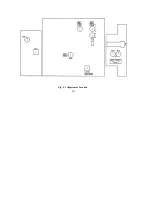
Please change jump wire J108 to the “ON” position (please refer to Fig. 5-1).
10
Ec
Ir
Io
×
=
Содержание Iso-tech IPS 303A
Страница 8: ...E5 FIG 3 1 Front Panel...
Страница 9: ...E6 FIG 3 2 Rear Panel...
Страница 13: ...E10 Fig 4 2 Connecting Two Power Supplies in Series...
Страница 15: ...E12 Fig 4 3 Connecting Two Power Supplies in Parallel...
Страница 20: ...E17 Fig 5 1 Adjustment Location...
Страница 21: ...E18 Fig 5 2 Adjustment Location...