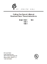
RP 1062 Скачать руководство пользователя страница 7

5

Figure 8

Figure 9

Figure 10

6. MAKE ELECTRICAL

CONNECTIONS

Remember

  to disconnect the power.

Follow the steps below to connect the fan to your 

household wiring. Use the wire connecting nuts 

supplied with your fan.  Secure the connectors with 

electrical tape. Make sure there are no loose 

strands or connections.

Step 1 Connect the fan supply (black) wire and 

light supply (blue) wire to the black household 

supply wire as shown in Figure 8.

Step 2. Connect the neutral fan (white) wire to the 

white neutral household wire.

Step 3 Connect green or bare copper wire from  

outlet box to the hanger bracket and downroll

ball green ground wires together. (Figure 8)

Step 4 After connecting the wires, spread them 

apart so that the green and white wires are on one 

side of the outlet box and the black and the blue 

wires are on the other side.

Step 5 Turn the connecting nuts upward and push 

the wiring into the outlet box. 

Figures 9 and 10 illustrate the wiring connections 

for optional wall control (The wire color out of wall 

control may vary, see wall control's installation 

manual for correct wire connections.)

WARNING: TO REDUCE THE RISK OF FIRE, 

ELECTRIC SHOCK, OR OTHER PERSONAL 

INJURY. MOUNT FAN ONLY ON AN OUTLET 

BOX OR SUPPORTING SYSTEM MARKED 


ACCEPTABLE FOR FAN SUPPORT.

H

W

E

UL

B

KL

B

KL

B

WH

GRN

WIRING

BOX

WIRING

BOX

GROUND TO

MOUNTING

BRACKET

AND DOWNROD

GROUND TO

MOUNTING

BRACKET

OR DOWNROD

BLUE

BLK

WH

WH

FAN

LIGHT

POWER LINES 120V

POWER LINES 120V

H

W

E

UL

B

KL

B

KL

B

WH

FAN

LIGHT

BLK

BLUE

WH

WH

LIGHT

SWITCH

GREEN GROUND

GREEN GROUND

GROUND TO

MOUNTING

BRACKET

OR DOWNROD

POWER LINES 120V

GREEN

GROUND

WIRING

BOX

H

W

E

UL

B

KL

B

KL

B

WH

FAN

LIGHT

WH

WH

BLUE

BLK

LIGHT

FAN

Содержание 1062

Страница 1: ...Ceiling Fan Owner s Manual Read and Save These Instructions Model 1062 1 1063 1 1064 1 1062 ...

Страница 2: ...ls Required Package Contents Safety Rules Mounting Options Hanging the Fan Making Electrical Connections Attaching the Fan Blades Operating Your Fan Care of Your Fan Troubleshooting TABLE OF CONTENTS 1 1 2 3 4 5 6 7 8 8 ...

Страница 3: ...embly d Motor housing e Blade bracket set f Screw package 1 Mounting hardware wood screws 2 screws 2 lock washers 4 wire nuts 3 washers 2 2 Blade attachment hardware screws 16 fiber washers 16 3 Motor housing hardware screw 4 4 Pull chain and fob Philips screw driver Blade screw driver 11 mm wrench Step ladder Wire cutters 1 TOOLS AND MATERIALS REQUIRED ...

Страница 4: ...blades are in motion Fan must be turned off and blades stopped before reversing blade direction 8 Avoid placing objects in the path of the blades 9 To avoid personal injury or damage to the fan and other items be cautious when working around or cleaning the fan 10 Do not use water or detergents when cleaning the fan or fan blades A dry dust cloth or lightly dampened cloth will be suitable for most...

Страница 5: ...ropriate fasteners and building materials The outlet box and its support must be able to fully support the moving weight of the fan at least 50 lbs Do not use plastic outlet boxes Figures 1 and 2 are examples of different ways to mount the outlet box To hang your fan where there is an existing fixture but no ceiling joist you may need an installation hanger bar as shown in Figure 3 Outlet box Figu...

Страница 6: ...ue wire from the fan to the black wire in the outlet box Then connect the white wire from the fan to the white wire from the outlet box Last connect the green wire from downrod to the green or ground wire from outlet box Fig 5 4 MOVE FAN INTO POSITION over the four mounting studs and secure with the provided washers and nuts Fig 6 5 INSTALL THE DECORATIVE HOUSING over the motor assembly and secure...

Страница 7: ...on one side of the outlet box and the black and the blue wires are on the other side Step 5 Turn the connecting nuts upward and push the wiring into the outlet box Figures 9 and 10 illustrate the wiring connections for optional wall control The wire color out of wall control may vary see wall control s installation manual for correct wire connections WARNING TO REDUCE THE RISK OF FIRE ELECTRIC SHO...

Страница 8: ...s and fiber washers as shown in Figure 11 Start screw into bracket Repeat for the two remaining screws Step 2 Tighten each screw Make sure the blade is straight Step 3 Fasten blade assembly to motor using the screws supplied Fig 11 Figure 11 Screws Blade Blades bracket Screws Fiber washers ...

Страница 9: ...eight number of fans and so on The slide switch controls directions forward switch down or reverse switch up NOTE Wait for fan to stop before changing the setting of the slide switch Warm weather Forward A downward airflow creates a cooling effect as shown in Fig 12 This allows you to set your air conditioner on a warmer setting without affecting your comfort Cool weather Reverse An upward airflow...

Страница 10: ...r each blade The distance deviation should be equal within 1 8 3 Use the enclosed Blade Balancing Kit if the blade wobble is still noticeable 4 If the blade wobble is still noticeable interchanging two adjacent side by side blades can redistribute the weight and possibly result in smoother operation WARNING TO REDUCE THE RISK OF PERSONAL INJURY DO NOT BEND THE BLADE ARM WHILE INSTALLING BALANCING ...

Отзывы: