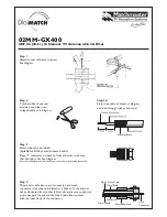
Figure 2.
1.1 GENERAL
The antenna should be installed clear of any
buildings, power lines, or any other antennas.
All holes for assembly have been pre drilled for
your convenience.
1.2 ASSEMBLING THE ANTENNA
SYSTEM
1.2.1 Tools and Accessories
You will need the following:
RF coax cable
Ground braid strap (PN FKN4314),
supplied with the Tuner
2ea Open end wrench ½”
1ea Open end wrench ¾”
1ea Open end wrench 11mm
1.2.2 Assembly Instructions
Step 1.
Remove all hardware from packaging as
shown in Figure 1.
Figure 1.
Step 2
. To simplify installation, both mast
sections have the same number and spacing of
holes. Insert the white insulator in the end of
one of the mast sections.
Step 3.
Line up the hole in the white insulator
with the hole in the mast.
Step 3.
Install the ground braid that is included
with the tuner between the tuner mounting
bracket and mast. (Refer to figure 2) Ensure the
locating pin on the white insulator is facing the
same side of the mast that the tuner will be
installed.
Step 4.
Install the tuner over the ground strap
using the center holes on the tuner mounting
brackets and secure with the provided bolts, nuts
and washers. Ensure the High Voltage connector
of the tuner is pointing in the direction of the
white insulator and is on the same side of the
mast as the locating pin in the top of the white
insulator. Attach grounding braid to ATU
Ground Terminal
(
Refer to figure 2)
Step 5.
Attach the smaller ring terminal of the
high voltage cable provided with this antenna kit
to the ATU RF output. While holding the high
voltage cable, push the rubber yoke cover
(provided with tuner) until it slips on the yoke.
Ensure High Voltage cable does not come in
contact with the mast. (Refer to figure 2)
Step 6.
Install the round stainless steel plate on
top of the white insulator, ensure the locking pin
lines up with the hole in the steel plate. Secure
with ½” bolt and washer. To avoid stripping the
threads, do not over tighten the bolt. (Refer to
figure 3)
Step 7.
Attach eyelet at end of High Voltage
Cable to the 3/8” hole in the side of the steel
Mounting Plate and secure with the provided
3/8” bolt, and lock washer. (Refer to figure 3)


