


10
S
ection
3— A
SSembly
& S
et
-U
p
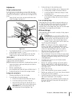
3.
Attach the end of the hose to the fitting on top of the filter.
Place the hose clamp at the base of the fitting, tighten securely
and cut the zip tie securing hose guard. See Figure 3-9.
Control
Valve
Return
Hose
Filter
Housing
To Reservoir Tank
Figure 3-9
Attaching The Log Tray
1.
Pull the beam lock on the beam support/latch bracket out
and pivot it down. Pull the vertical beam lock on the tank
and pivot it down. Carefully lower the wedge, beam, and
cylinder assembly to the horizontal position. Pull out and
rotate beam lock to secure beam in the horizontal position.
NOTE:
The hardware for attaching the log tray can be
found already inserted into the beam.
2.
Remove the tray mounting screws from the beam.
3.
Place a log tray assembly against the lower outside surface
of the beam flange and secure using the four self-tapping
screws previously removed. See Figure 3-10.
Log Tray
Screws
Figure 3-10
4.
Attach second tray support bracket assembly to the other
side of the beam using the instructions above.
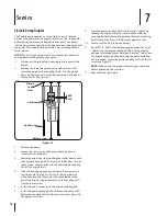
Attaching The Hoses
Suction Hose:
The suction hose is attached to the reservoir tank, beneath the
engine mounting bracket.
1.
Loosen the hose clamp on the free end of the hose.
Remove any protective insert from the end of the hose.
2.
Remove the protective cap from the fitting on the bottom
of the pump (some oil may flow from pump).
3.
Attach the end of the suction hose to the fitting on the
bottom of the pump. See Figure 3-8.
Hose Clamp
Pressure Hose
Suction Hose
To Reservoir Tank
To Filter
Housing
Figure 3-8
4.
Place the hose clamp at the base of the fitting and tighten
securely.
Pressure Hose:
The pressure hose is attached to the control valve at the factory.
1.
Route the pressure hose between the beam and the
tongue to the top of the pump.
2.
Remove the protective hose cover.
3.
Secure the pressure hose to the pump and cut the zip tie
securing hose guard. See Figure 3-8.
Return Hose:
The return hose is attached to the control valve at the factory.
1.
Loosen the hose clamp on the free end of the hose.
Remove any protective insert from the end of the hose.
2.
Remove the protective cap from the top of the filter head.
Содержание RM 33 LS
Страница 22: ...Notes 10 22...
Страница 23: ...23 Section 10 Notes...


