8
S
ection
2— A
SSembly
& S
et
-U
p
2.
Secure the jack stand in position with the clevis pin and
spring clip. See Figure 3-3.
3.
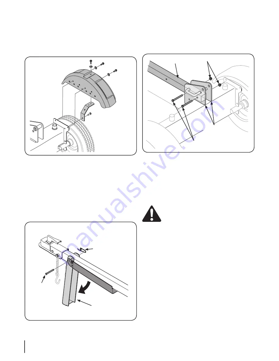
Remove two hex bolts and hex nuts from the tank bracket
and remove the piece of wood (if present) between the tank
brackets. See Figure 3-4.
Hex Nuts
Hex Bolts
Tongue
Tank Brackets
Figure 3-4
4.
Align the holes in the tongue with the holes in the tank
bracket and secure with the hardware just removed. See
Figure 3-4.
NOTE:
The high pressure hose, which runs from the gear
pump to the bottom of the control valve, must be
above
the tongue assembly.
Positioning the Beam
WARNING!
Take extra care when raising and
lowering the beam as it is fairly heavy. Having a
second person assist with raising or lowering the
beam is recommended. Be sure to keep hands away
from any possible pinch points.
1.
Remove any bolts or straps securing the beam and cylinder
to the bottom of the crate.
2.
Remove the wood (if present) between the wedge and the
end plate by cutting the cable tie that secures it. Cut the
strap near the hose on the front of the cylinder that secures
it to the beam weld bracket. Be careful not to damage the
hose.
3.
Remove the vertical beam pin (see inset of Figure 3-5).
4.
Position the Beam and cylinder assembly in front the
reservoir assembly as shown in Figure 3-5 and secure it
with the pin and bowtie clip removed in step 3.
5.
Pivot the beam to the horizontal position until it locks into
place, being sure to avoid any possible pinch points. See
Figure 3-5.
Attaching the Fenders
NOTE:
The fender may be pre-assembled to the fender bracket
by a self-tapping screw, flat washer and lock nut at the factory.
1.
Remove the self-tapping screws and the flat washers from
one side of the reservoir tank. See Figure 3-2.
Figure 3-2
2.
Place the fender and the fender bracket up against the
reservoir tank and align with the holes.
3.
Secure the fender and fender bracket to the reservoir tank
with the hardware removed in step one. See Figure 3-2.
4.
Install the second fender using the instructions above.
Attaching the Tongue Tube
1.
Remove the spring clip and clevis pin from the jack stand
on the tongue and then pivot the jack stand towards the
ground into the operating position. See Figure 3-3.
Spring Clip
Clevis Pin
Jack Stand
Figure 3-3
Содержание R 21 LS
Страница 21: ...Notes 11 21...
Страница 22: ...22 Section 11 Notes...
Страница 23: ...23 Section 11 Notes...


