12V FUEL TRANSFER PUMP OWNER’S MANUAL
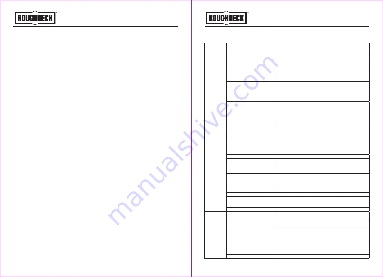
TROUBLE SHOOTING
5 of 6
12V FUEL TRANSFER PUMP OWNER’S MANUAL
OPERATION INSTRUCTIONS
1. If using flexible tubing, attach the ends of the tubing to the tank(s). In the absence of an
appropriate slot, solidly grasp the delivery tube before beginning dispensing.
2. Before starting the pump, make sure that the delivery valve is closed (dispensing nozzle or
line valve).
3. Turn the ON/OFF switch to ON. The by-pass valve allows functioning with the delivery closed
for only brief periods.
4. Open the delivery valve, solidly grasping the end of the tubing.
5. Close the delivery valve to stop dispensing.
6. When dispensing is finished, turn off the pump.
MAINTAINANCE
Under normal working conditions, the noise emission from all models does not exceed the
value of 80dB at a distance of three feet from the electric pump.
Transportation
When the pump is in transit, do not expose the pump to direct sunlight and avoid rain, falling,
corrosive substances, etc.
Storage
①
. Store the pump in a dry place with good ventilation. Do not expose it to excessive heat,
humidity or sunlight. Never let it touch any corrosive substances.
②
. Store it out of the reach of children.
4 of 6
Problem
Possible Cause
Corrective Action
Motor does not
run
1. Fuse blown
1. Open the terminal box, check the fuse, if blown, replace
2. Switch defective
2. Remove switch cover plate and inspect switch. Replace if necessary
3. Motor burned out
3. Replace motor as described in the repair section
4. Switch or electrical connections
faulty
4. Inspect for damaged motor protector, defective wiring or switch, or
improper electrical connections. Replace as needed and reinstall
Motor runs but
does not pump
1. Suction pipe clogged, damaged,
or missing
1. Remove pump from tank, inspect suction pipe. Clean or replace as
necessary
2. Gear cover plate or o-ring
damaged
2. Remove and inspect the cover plate and o-ring, replace, as necessary,
refer to the repair section on servicing o-ring
3. Strainer clogged or defective
3. Remove strainer cover plate, remove and clean strainer, install again
4. Bypass poppet o-ring worn or missing 4. Inspect o-ring using instructions in the repair section. Replace, if necessary
5. Bypass poppet o-ring dirty
5. Remove poppet assembly and clean poppet and cavity
6. Bypass poppet binding or
damaged
6. Using instructions in the repair section. Remove the bypass poppet, spring
and o-ring. Clean cavity, inspect and replace components, as necessary
7. System air leak
7. Tighten all pump fitting and connections. Inspect suction pipe for leaks
or damage
8. System air lock
8. This can occur if external filter, meters, or an off-the-shelf automatic
nozzle is used. To correct, remove the pipe plug in the top outlet port
and fill the gear cavity with fuel. Use of a factory –supplied automatic
nozzle is recommended
9. Poor connections or low voltage
9. Make sure electrical connections are secure. Also check battery voltage
10. Fuel level low
10. Fill tank
11. Motor running backwards due to
incorrect polarity
11. Connect red wire to positive (+) ungrounded side of battery. Gear with
key should turn counterclockwise
Low flow rate
1. Poor connections or low voltage
1. Make sure electrical connections are secure, also check battery voltage
2. Strainer partially clogged
2. Remove the strainer cover plate. Remove and clean the strainer. Install again
2. Strainer partially clogged
3. Remove pump from tank. Inspect suction pipe. Clean or replace, as
necessary
4. Fuel tank empty
4. Fill tank
5. Using off-the-shelf automatic
nozzle
5. Factory-supplied automatic nozzle is recommended
6. System air leak
6. Tighten all pump fittings and connections. Inspect suction pipe for leaks
or damage. Replace, as necessary
7. Bypass poppet spring weak
7. Using instructions in the Repair Section, remove the bypass poppet and
inspect spring, replace , if necessary
Motor stalls
when operation
in bypass mode
1. Motor protector activated
1. Turn off switch. Allow motor to cool, then turn on switch.
2. Gears locked
2. Remove gear cover plate and inspect gears and drive key. Make sure
gears turn freely with the key removed. Replace, if worn.
3. Wiring defective
3. Use wiring instructions in the installation section to ensure proper connections
4. Bypass poppet binding or
damaged
4. Using instructions in the Repair section, remove the bypass poppet,
spring, and o-ring. Clean cavity. Inspect components and replace, as
necessary
5. Motor defective
5. Replace motor as described in the repair section
Switch fails to
operate motor
1. Switch or electrical connections
faulty
1. Inspect for damaged motor protector, blown fuse, defective wiring or switch,
or improper electrical connections. Replace as needed and re-install
2. Motor burned out
2. Replace motor as described in the repair section
3. Motor protector activated
3. Turn off switch. Allow motor to cool , then turn on switch
Rapid
overheating of
motor
1. Duty cycle too long
1. Pump operation should not exceed the standard duty cycle of 30minutes
on, and 30minutes OFF. Allow the pump to cool for 30minutes.
2. Strainer clogged,
2. Remove strainer cover plate. Remove and clean strainer. Install again.
3. Suction pipe clogged or damaged 3. Remove pump form tank. Inspect suction pipe. Clean or replace, as necessary.
4. Gears worn
4. Remove gear cover plate and inspect gears and drive key. Make sure
gears turn freely with key removed. Replace, if necessary.
5. Fuel level low
5. Fill tank
6. Running too long in bypass mode 6. Limit bypass operation to 5 minutes.


