background image

RMS-LOG Wireless / LAN Data Loggers 


E-M-RMS-MLOG-868-V1_0.docx 

Instruction Manual 


Table of Contents 


1


Overview ................................................................................................................................................. 3


1.1


RMS System Overview ........................................................................................................................ 3


1.2


Device Overview .................................................................................................................................. 4


1.3


RMS Mini Data Logger ......................................................................................................................... 5


1.4


Power Supply ....................................................................................................................................... 5


1.5


Measured Parameters .......................................................................................................................... 6


1.6


RTCC (Real Time Clock Calendar) ...................................................................................................... 7


1.7


Data Logging and Measurement Interval ............................................................................................. 7


1.8


Indicator and Button ............................................................................................................................. 7


1.9


Interface ............................................................................................................................................... 8


1.10


Software Compatibility ......................................................................................................................... 8


2


Dimensions ............................................................................................................................................ 9


3


Installation ............................................................................................................................................ 10


4


Electrical Connections ........................................................................................................................ 12


4.1


Battery ................................................................................................................................................ 12


5


Operation .............................................................................................................................................. 13


5.1


Default Configuration ......................................................................................................................... 13


5.2


Integration in the RMS-WEB Software ............................................................................................... 13


5.3


Function Overview ............................................................................................................................. 15


6


Maintenance ......................................................................................................................................... 16


6.1


Battery Replacement .......................................................................................................................... 16


7


Firmware Update.................................................................................................................................. 17


8


Technical Specifications ..................................................................................................................... 18


9


Accessories ......................................................................................................................................... 20


9.1


RMS Accessories ............................................................................................................................... 20


10


Additional Documents ......................................................................................................................... 21


11


Document Version ............................................................................................................................... 22


© 2016 

 ROTRONIC AG 

 Bassersdorf 

 Switzerland 


Page 2 of 22


Содержание RMS

Страница 1: ...RMS Mini Wireless Data Logger 2016 ROTRONIC AG Bassersdorf Switzerland ...

Страница 2: ...rval 7 1 8 Indicator and Button 7 1 9 Interface 8 1 10 Software Compatibility 8 2 Dimensions 9 3 Installation 10 4 Electrical Connections 12 4 1 Battery 12 5 Operation 13 5 1 Default Configuration 13 5 2 Integration in the RMS WEB Software 13 5 3 Function Overview 15 6 Maintenance 16 6 1 Battery Replacement 16 7 Firmware Update 17 8 Technical Specifications 18 9 Accessories 20 9 1 RMS Accessories ...

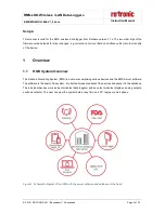
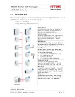
Страница 3: ...The Rotronic Monitoring System RMS is a network comprising various devices and the RMS Server software The software is the heart of the system It collects all measured data of the devices and saves it in the database The individual devices work as input modules data loggers and as output modules displays analog outputs switched outputs The user can view the system data at any time on a PC laptop o...

Страница 4: ...so available as variant with two solid state relays in order for example to switch alarm lamps Input Module Records voltage or current signals from analog devices such as particle counters flow transmitters or CO2 probes For example HF5 transmitter humidity temperature AF1 transmitter air flow CO2 transmitter CO2 PF4 transmitter differential pressure Temperature Logger The loggers can be equipped ...

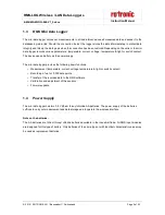
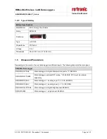
Страница 5: ...es the following basic functions o Measurement temperature current voltage temperature light or switch contact o Recording of up to 10 000 data points o Transfer of the recorded data to the RMS software o Calibration and adjustment of the sensors o Firmware update 1 4 Power Supply The mini data logger has two 3 6 V lithium thionyl chloride AA batteries The power supply of the batteries suffices to...

Страница 6: ... different inputs The following table lists the main types RMS Mini Data Logger RMS MLOG T 868 Mini data logger integrated temperature probe C 868 MHz RMS MLOG T10 868 Mini data logger external NTC probe C 868 MHZ NTC must be ordered separately RMS MADC 868 A Mini data logger 1 x analog input 0 20 mA 868 MHz RMS MADC 868 V Mini data logger 1 x analog input 0 10 V 868 MHz RMS MLOG LGT 868 Mini data...

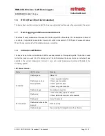
Страница 7: ...ion of the operating state The button is used to start the device or switch it off in battery mode The LED indicates the device status and whether it was possible in the current measurement interval to carry out a valid measurement and send the data to the monitoring system LED Status Indicator Status LED Function Meaning Connected Flashes green Status OK Flashes green when button pressed 1 time v...

Страница 8: ...mpletely via the wireless interface 1 10 Software Compatibility The logger is designed for use with the RMS server software local installation or Rotronic Cloud The data logger can alternatively also be operated with the RMS configuration software standalone software 2016 ROTRONIC AG Bassersdorf Switzerland Page 8 of 22 ...

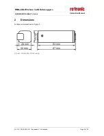
Страница 9: ...Wireless LAN Data Loggers E M RMS MLOG 868 V1_0 docx Instruction Manual 2 Dimensions All dimensions are shown in Figure 2 Figure 2 Dimensions of the housing 2016 ROTRONIC AG Bassersdorf Switzerland Page 9 of 22 ...

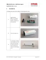
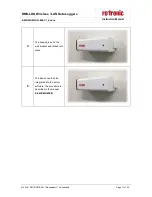
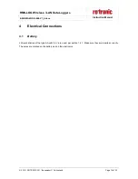
Страница 10: ...step 1 Insert the battery Make sure it is inserted correctly The poles are marked on the battery and on the electronics 2 Put on the housing cover 3 The wall bracket is fastened to the wall with screws The screws may only protrude so far that the device can click into place properly when put on to the fastened cover 2016 ROTRONIC AG Bassersdorf Switzerland Page 10 of 22 ...

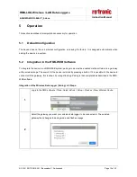
Страница 11: ...docx Instruction Manual 4 The housing is put in the wall bracket and clicked into place 5 The device can then be integrated into the server software The procedure is described in the manual E SM RMS WEB 2016 ROTRONIC AG Bassersdorf Switzerland Page 11 of 22 ...

Страница 12: ...ion Manual 4 Electrical Connections 4 1 Battery Lithium batteries of the type AA with 3 6 V are used per section 1 4 1 Make sure they are inserted correctly The poles are marked on the battery and on the electronics 2016 ROTRONIC AG Bassersdorf Switzerland Page 12 of 22 ...

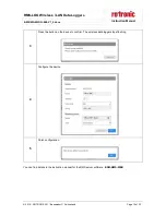
Страница 13: ...ust be enabled via the software on a gateway within wireless range The search for the device is started by pressing a button If it is possible for the device to connect with the gateway this is shown by orange flashing Pairing is then completed as described in the RMS WEB software Integration of the Wireless Data Logger Pairing in 5 Steps 1 Log into the RMS software Cloud Select Extras Setup Devic...

Страница 14: ...nual 3 Press the button on the device to confirm The wireless data logger stops flashing 4 Configure the device 5 Finish configuration You can find details in the instruction manual for the RMS server software E SM RMS WEB 2016 ROTRONIC AG Bassersdorf Switzerland Page 14 of 22 ...

Страница 15: ...easurement Save measured data The measured values of every measurement are saved in the internal ring memory 10 000 pairs of measured values If the data cannot be sent to the server software directly they are kept in the device and then sent later as soon as the connection to the server software has been restored Firmware update The firmware of the device can be updated directly via the RMS server...

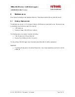
Страница 16: ...ows automatically when the battery needs to be replaced LED flashes red System message in the RMS server software The following steps are necessary to replace the battery Take the device out of the wall bracket Remove the old battery and insert a new one The time setting of the data logger is synchronized automatically after the battery replacement Important The battery life depends on the ambient...

Страница 17: ...MS MLOG 868 V1_0 docx Instruction Manual 7 Firmware Update The firmware can be updated with the RMS server software Firmware updates are available for downloading on the ROTRONIC website 2016 ROTRONIC AG Bassersdorf Switzerland Page 17 of 22 ...

Страница 18: ...orage and transport conditions 40 30 C 0 95 RH Data memory 10 000 measured values Interfaces Wireless 868 MHz Wireless range 20 50 m indoors Power supply Supply voltage Battery Polarity protection Yes Battery life 3 years at 23 C and interval of 1 minute Start Time and Measurement Interval Start time Wireless logger 1 s typical Measurement interval 10 s to 15 min Housing Specifications Housing mat...

Страница 19: ...ve 2014 30 EU EN 61000 6 1 2007 EN 61000 6 2 2005 EN 61000 6 3 2007 A1 2011 AC 2012 EN 61000 6 4 2007 A1 2011 EN 61326 1 2013 Performance criterion www rotronic com Soldering material Lead free RoHS Directive 2011 65 EU FDA GAMP directives FDA CFR21 Part 11 GAMP5 2016 ROTRONIC AG Bassersdorf Switzerland Page 19 of 22 ...

Страница 20: ...ion Manual 9 Accessories 9 1 RMS Accessories Order Code Description RMS GW 868 Gateway LAN to 868 MHz AC1321 Mounting kit with Allen key and mounting cone RMS NPK Network planning kit wireless dongle RMS mini logger 2016 ROTRONIC AG Bassersdorf Switzerland Page 20 of 22 ...

Страница 21: ...cument Name Contents E IM RMS WEB Instruction Manual System Installation E SM RMS WEB Instruction Manual System Startup E OM RMS WEB Instruction Manual System Operation E M RMS GW 868 Instruction Manual Gateway E M RMS LOG Instruction Manual Data Logger 2016 ROTRONIC AG Bassersdorf Switzerland Page 21 of 22 ...

Страница 22: ...S LOG Wireless LAN Data Loggers E M RMS MLOG 868 V1_0 docx Instruction Manual 11 Document Version Version Date Notes V1_0 October 2016 First version 2016 ROTRONIC AG Bassersdorf Switzerland Page 22 of 22 ...

Отзывы: