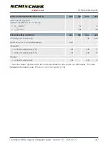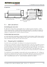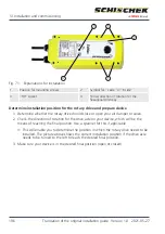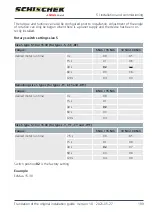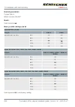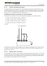
9. Turn the switch (S) to position 02 (small torque) or 07 (large torque). Keep the button
(T) pressed for at least 3 seconds. The drive moves independently to both final posi-
tions and detects the blocking positions. The LED flashes green during the adjustment.
The adjustment lasts approx. 60 s for size S and 180 s for size M.
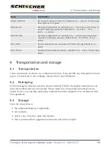
10-position-switch (S)
Button (T)
3-colour LED
ð
The drive moves slowly through the complete turning range in both directions to es-
tablish its precise final positions.
10. Connect all the remaining terminals and turn the switch (S) to the desired position.
ð
The selected parameters will be executed during the next regulation/setting func-
tion.
ð
The rotary drive has now been correctly installed.
5.3.1
Parameter setting
For parameter setting, all rotary drives are equipped with a 10-position switch, a button and
a 3-colour LED.
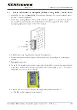
These controls are located on the cable side behind the two small, central blanking plugs or
pressure-compensation elements (carefully twist in and out). The blanking plugs need to be
removed to operate.
10-position-switch (S)
Button (T)
3-colour LED
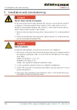
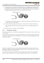
Operation / parameter setting can be undertaken despite pending voltage applied to the
rotary drive. Afterwards, the removed blanking plugs must be inserted again to ensure the
drive does not lose its IP protection class.
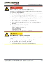
The switch and button are operated using a screwdriver. Never apply force by vigorously
pressing and/or twisting as this can cause irreparable damage to the control electronics.
5 | Installation and commissioning
198
Translation of the original installation guide · Version 1.0 · 2021-05-27


