rotork ROMpak Series Скачать руководство пользователя страница 11

Keeping the World Flowing

11

Commissioning

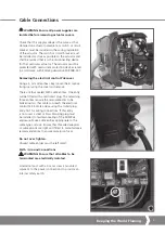
 WARNING: Ensure all power supplies are 

isolated before removing actuator cover. Caution 
is required when removing cover as motor and 
heater may be hot. On actuators with single- 
phase supplies the motor start capacitor may 
retain a hazardous residual charge.

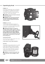
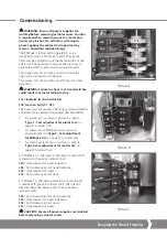
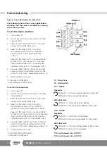
The ROMpak is factory set to operate 90º and is  
designed to stop on limit at each end of travel, the  
limits may be adjusted to suit the characteristics of the 
valve. It will be necessary to remove the top cover to 
expose the switch mechanism when adjusting cam. 
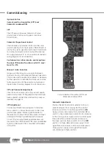
Two travel cams LS1 and LS2 are set to control the  
open and close position of the valve.
Two travel cams LS3 and LS4 are set for end of travel 
indication.

 WARNING: Failure to check / set travel switches 

could result in actuator failing to stop.

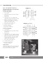
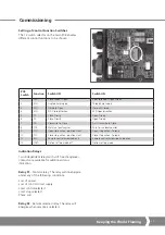
For Clockwise to Close Actuators 

PCB Function Switch 7 OFF. 

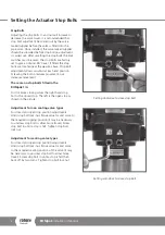
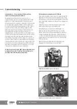
The travel cams are preset at the factory, when additional 
adjustments are needed, follow items described below:

• 

For plastic cam (as shown in picture A), refer to  

‘Type 1 - Cam adjustment for plastic cam’ 

on 

page 12 to adjust Cam.

• 

For metal cam of ROMpak 1/A (as shown in  
picture B), refer to 

‘Type 2 - Cam adjustment  

for ROMpak 1/A’

 on page 13 to adjust Cam.

• 

For metal cam (as shown in picture C), refer to 

‘Type 3-cam adjustment for metal cam‘ 

on  

page 14 to adjust Cam. 

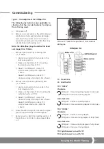
For ROMpak 1-7, the rotation direction of output shaft  
is identical with position indicator shaft.

LS4:

  Clockwise end of travel indication

LS3:

  Anti-clockwise end of travel indication

LS2:

  Clockwise end of travel 

LS1:

  Anti-clockwise end of travel

For ROMpak A, the rotation direction of output shaft 
is reverse with position indicator shaft. The rotation 
direction described below is the same as position 
indicator shaft.

LS4:

  Anti-clockwise end of travel indication

LS3:

  Clockwise end of travel indication

LS2:

  Anti-clockwise end of travel 

LS1:

  Clockwise end of travel 

 CAUTION: Ensure all power supplies are isolated 

before removing actuator covers. 

LS4

LS3

LS2

LS1

TC4

TC3

TC2

TC1

Picture A

Picture B

Picture C

LS4

LS3

LS2

LS1

TC4

TC3

TC2
TC1

LS4

LS3

LS2

LS1

TC4

TC3

TC2

TC1

Содержание ROMpak Series

Страница 1: ...Keeping the World Flowing ROMpak Series Installation Manual Valve Actuators...

Страница 2: ...nd safety 3 Operating by hand 4 Electrical operation 5 Indication 6 Mounting the actuator 7 Setting the actuator stop bolts 8 Cable connections 9 Commissioning 11 Maintenance and troubleshooting 19 We...

Страница 3: ...ng on the remote control signal status and configuration Storage If your actuator cannot be installed immediately store it in a dry place until you are ready to connect the incoming cables If the actu...

Страница 4: ...ith respect to handwheel operation of Rotork electric actuators under no circumstances should any additional lever device such as a wheel key or wrench be applied to develop more force when closing or...

Страница 5: ...can be turned to open and close the actuator Clockwise rotation will close the actuator Anti clockwise rotation will open the actuator When the knob is released it will return to the central position...

Страница 6: ...andard configuration green is closed and red is open Located on the side face of the control Pak three LED s also indicate valve position and status The standard configuration is as follows Red Valve...

Страница 7: ...the picture Actuator to valve fixing must conform to MaterialSpecification ISO Class 8 8 yield strength 628 N sq mm WARNING Do not lift the actuator and valve combination via the Actuator Always lift...

Страница 8: ...movement There are no stop bolts fitted in the ROMpak 1 A For clockwise closing valves the right hand stop bolt is the closed stop The left is the open stop as shown in the picture Adjustment for non...

Страница 9: ...ring the cover and remove There are four sealed M20 cable entries One entry will be fitted with a red transit plug The remaining three entries require the removable disc to be broken out so that cable...

Страница 10: ...Connections On the end of the main PCB there is a terminal rail for power connections The terminals are rated for 24 12 AWG cross section up to 2 5 mm Connecting the Control Terminals Refer to the wi...

Страница 11: ...ed follow items described below For plastic cam as shown in picture A refer to Type 1 Cam adjustment for plastic cam on page 12 to adjust Cam For metal cam of ROMpak 1 A as shown in picture B refer to...

Страница 12: ...g Open limit switch is now set Clockwise for ROMpak A Anti clockwise for ROMpak A To set the close position a Turn power off b Use manual override to turn valve to the fully closed position c Remove c...

Страница 13: ...into the hole of self locking nut Note the Allen hex key should be flat head and longer than 100mm c Set fully open position by following item 1 2 3 below 1 Use manual override to turn valve to the f...

Страница 14: ...o the fully closed position c Remove cover and loosen the TC2 set screw using a 2 5 mm Allen hex key d Case 1 If the roller of LS2 is touching the cylindrical surface of TC2 rotate TC2 clockwise slowl...

Страница 15: ...closed position Locate cam TC1 and adjust until switch LS1 just operates Locate cam TC3 and adjust so the cam operates the switch LS3 just before LS1 to ensure correct indication at end of travel The...

Страница 16: ...STOP position During this procedure the 4 LED indicators will flash in sequence Set DIP switch No 12 to OFF The position calibration is now complete If the travel cams have NOT been adjusted and remai...

Страница 17: ...tion position Limit Close stop action Torque 11 RSC Remote control hardwired only Remote control hardwired and option 12 FOLO Option setting mode off Option setting mode Commissioning Setting of Contr...

Страница 18: ...nt The CPT and Folomatic are factory set and usually need no adjustment If the gearbox stop bolts have been adjusted conduct the Initialisation process as descibed on page 12 CPT Adjustment Connect mu...

Страница 19: ...e on our website at www rotork com The actuator gearbox and switch unit contain no serviceable parts WARNING All electrical supplies to the actuator must be isolated before any maintenance is carried...

Страница 20: ...y latest version release visit our website at www rotork com The name Rotork is a registered trademark Rotork recognises all registered trademarks Published and produced in the UK by Rotork Controls L...

Отзывы: