A4
US
US
A4
US
A4
US
A4
A4
US
US
A4
US
A4
A4
US
IQ3 Full Configuration Manual – Section: Settings
11
2.2 Settings – Indication
Settings
Limits
Indication
Control
ESD
Security
Defaults
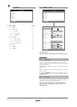
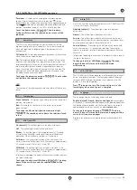
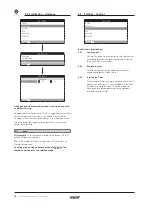
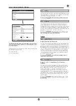
Instruction is provided on:
2.2.1
Contacts
2.2.2
Local display
2.3.3
Analogue
Settings
Limits
Indication
Control
ESD
Security
Defaults
Indication
Contacts
Local Display
Analogue
Contacts
Monitor Relay
Mode
Available
S1
Function
Closed Limit
Contact
N/O
N/C
Position
0%
S2
Function
Open Limit
Contact
N/O
N/C
Position
0%
S3
Function
Closed Limit
Contact
N/O
N/C
Position
0%
S4
Function
Open Limit
Contact
N/O
N/C
Position
0%
1/37
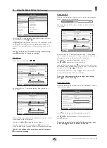
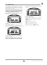
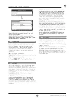
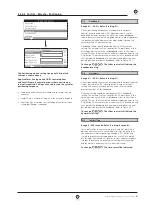
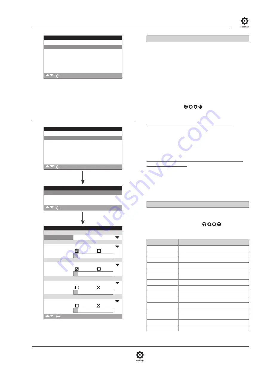
The Monitor Relay and S contact settings page is shown in
their default setting.
Refer to actuator wiring diagram for available contacts.
1/37
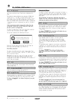
Monitor Relay – Mode
The monitor relay provides remote indication of actuator status.
It provides a volt free change over contact, refer to actuator
circuit diagram. There are 2 modes that can be set:
Available (default)
– Actuator available for remote control.
Monitors power supplies, motor thermostat, detected internal
fault and remote control selected. A loss in one or more will
cause the monitor relay to de-energise indicating "not available"
for remote control.
Fault
– Actuator fault. Monitors power supplies, motor
thermostat and detected internal fault. A loss in one or more
will cause the monitor relay to de-energise indicating "actuator
fault".
To change the mode, . The drop down list box
will close and the selected mode will be shown:
S Contact function, contact type and position
Each relay contact can be set to one of the functions shown
in the table below and its contact type can be set as Normally
Open (NO) or Normally Closed (NC). If Pos % Open function is
selected, the position at which the relay operates can be set. For
all other functions the position control slider will be greyed out.
Standard Contacts S1-S4, Option S5-S8 and S9-S12
Contacts when fitted
The method for setting all S contacts is the same. S1 to S4 are
fitted as standard. A further 8 extra contacts are available as
options grouped: S5 to S8 and S9 to S12, refer to actuator wiring
diagram. If extra contacts are fitted their configuration screens
are accessed by scrolling down. If not fitted their configuration
settings will be greyed out.
2/37
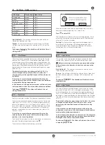
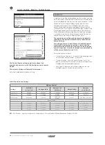
Contact Function
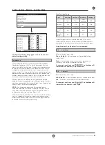
The available contact functions included in the drop down list
box are shown below.
To change the contact function,
. The drop
down list box will close and the selected function will be
shown:
Function
Indication:
Disabled
Contact disabled
Closed Limit
Closed limit position (exact)
Open Limit
Open limit position (exact)
End Position
Both Closed and Open Limit positions
Pos % open
Set position mid-travel – opening and closing
Mid Travel
Not at Closed or Open Limits
Motor Running
Motor running
Closing
Travelling in the close direction - motor or handwheel
Opening
Travelling in the open direction - motor or handwheel
Moving
Travelling – motor or handwheel
Handwheel
During handwheel operation
Blinker
Travelling (make/break at 1 second intervals)
Valve Alarm
On torque trip mid-travel or motor stall condition
Torque Trip CL
Torque trip closing - any position
Torque Trip OP
Torque trip opening - any position
Continued over page
2.2.1 Indication – Contacts
Содержание IQ Multi-Turn
Страница 2: ...2...


