ENGLISH
19
3
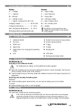
Technical Data charger and battery
(B)
Battery:
Charger:
U = Voltage
U1 = Input voltage
C = Capacity
f1 = Input frequency
W = Weight
P1 = Input power
Ic = Charge current
U2 = Charging voltage
t
= Approx. charging time (90% full)
I2 = Max. charge current
Charging voltage ............................
20,75 V DC
Nc = No. of battery cells
Charging temperature .....................
0° - 50° C
W = Weight
Max. discharging temperature. .......
5° - 50° C
Pay attention to the electrical outlet
voltage! Check the label on the bottom
of the charger!
Recharge battery pack before first use!
4
Function of the Unit
4.1
Overview RO RH4000
(A)
1
Additional handle
8
Eyelet for securing the carrying strap
2
Tool lock
9
Rotation selector switch
3
SDS chuck
10
Trigger
4
Depth stop
11
Handle
5
Switch button (for changing the operating
mode)
12
Battery pack
6
Lock
13
LED lights
14
Battery pack release button
4.2
Start of operation
RO RH4000 (fig. A):
Assembly of the additional handle:
For safety reasons, always use the additional handle supplied!
Open the clamping ring by turning the additional handle (1) counter-clockwise. Push the ad-
ditional handle onto the collar of the machine.
Insert the depth stop (4). Securely tighten the additional handle at the angle required for the
application.
Removing and inserting the battery pack:
Removal:
Press the battery pack release button (14) and pull the battery pack (12) forwards.
To insert:
Slide the battery pack (12) in until it engages.
4.3
Operating
RO RH4000 (fig. A):
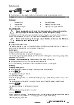
The machine's multifunctional monitoring system:
If the machine switches off automatically, the machine electronics have activated
automatic protection mode. A warning signal sounds (continuous beeping). The
beeping stops after a maximum of 30 seconds or when the trigger (10) is released.


