


12 • Panel Row Module Cabling
4.
Connect and secure one of the
Module Control Link Cable
to the
NEXT
port on the second module
d
.
5.
Connect and secure the other end of the
Module Control Link Cable
to the
PREV
port on the third module
e
.
6.
Connect and secure one of the
Module Control Link Cables
to the
NEXT
port on the third module
e
.
7.
Connect and secure the other end of the
Module Control Link Cable
to the
PREV
port on the fourth module
f
.
8.
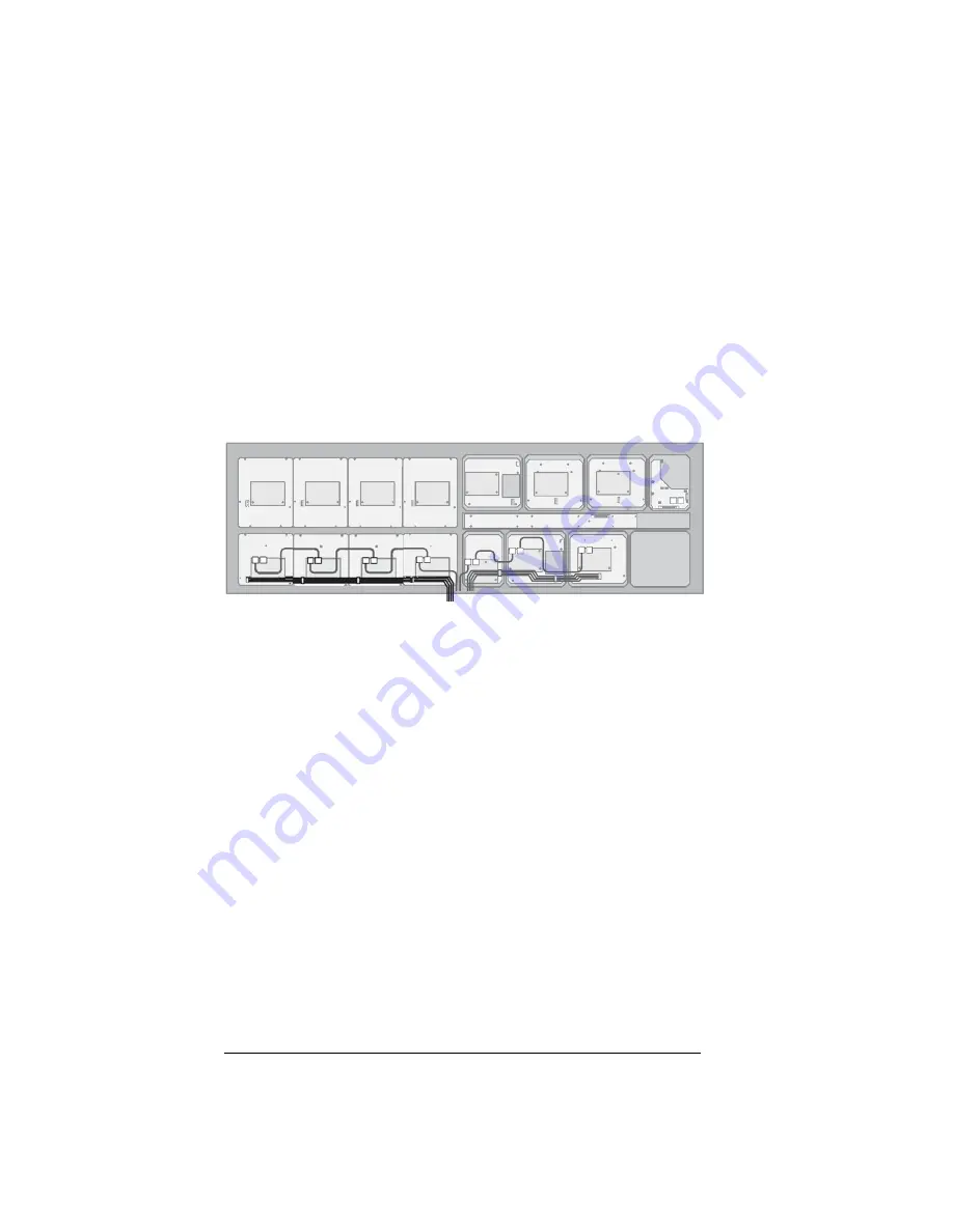
Connect and secure the existing
Module Power Cable
to the
Power
connector on the first module (
). This 4-conductor ribbon
cable delivers power to all the modules in the row.
Figure 9 Module Power Cable — Vision 2X
9.
Connect and secure the
Module Power Cable
to the remaining
modules.
This completes the procedure for cabling the Crosspoint modules. With the
panel row modules installed and cabled, you must now either install the
mnemonics or the Mnemonic Blank plate.
Power Cable
Front of Control Panel
Содержание Vision 4800DR-325-02
Страница 1: ...Ross Video Limited Panel Row Addition Installation Guide V I S I O N...
Страница 15: ...Panel Row Setup 15 Notes...


