Device functions
Page 42
RES-5008
Version 2
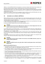
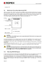
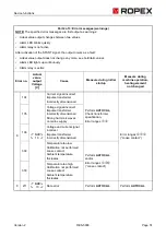
While executing the function AUTOCOMP, the “OUTPUT” LED blinks several times and the actual value output
(terminals 17+7) goes to 0…3 °C (i.e. approx. 0 VDC).
9.15
Temperature diagnosis
An additional temperature diagnosis can be activated with the ROPEX visualisation software (
"USB-interface for visualisation software ROPEXvisual
" on page 45). The RESISTRON
®
Temperature Controller
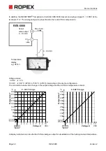
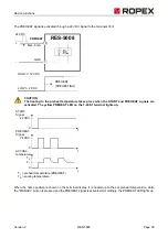
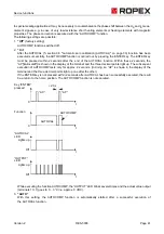
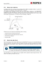
RES-5008 checks if the ACTUAL temperature within an settable tolerance band “OK window” is found on either
side of the SETPOINT temperature. The lower (
) and upper (
) tolerance band limit are set at
the factory to -10 K and +10 K, respectively. These values can be set separately from each other with the ROPEX
visualisation software.
After activation of the START signal, if the ACTUAL temperature is found within the specified tolerance band,
the temperature diagnosis is switched on. If the ACTUAL temperature leaves the tolerance band, the related error
nos. 307, 308 are output and the alarm output switches on (
section 9.25 "Error messages" on page 48).
If the temperature diagnosis has not been activated before the START signal is deactivated (i.e. the ACTUAL tem-
perature has not exceeded the lower tolerance band limit or has not dropped below the upper tolerance band limit),
the related error nos. 309, 310 are output and the alarm relay switches on.
A delay time (0...9.9 sec.) can also be set with the ROPEX visualisation software. After the lower tolerance band
limit is exceeded, the temperature diagnosis takes place only after the parametrised delay time has expired.
As a result, the temperature diagnosis can be intentionally suppressed, e.g. during a temperature drop caused
by closing the tool.
Function
Key “ENTER”
pressed
“AC”
t
t
0
0
AUTOCAL
AUTOCOMP
Δϑ
lower
Δϑ
upper
Setpoint
S
Δϑ
lower
S
Δϑ
upper
ACTUAL temperature
Time
Alarm
307


