background image

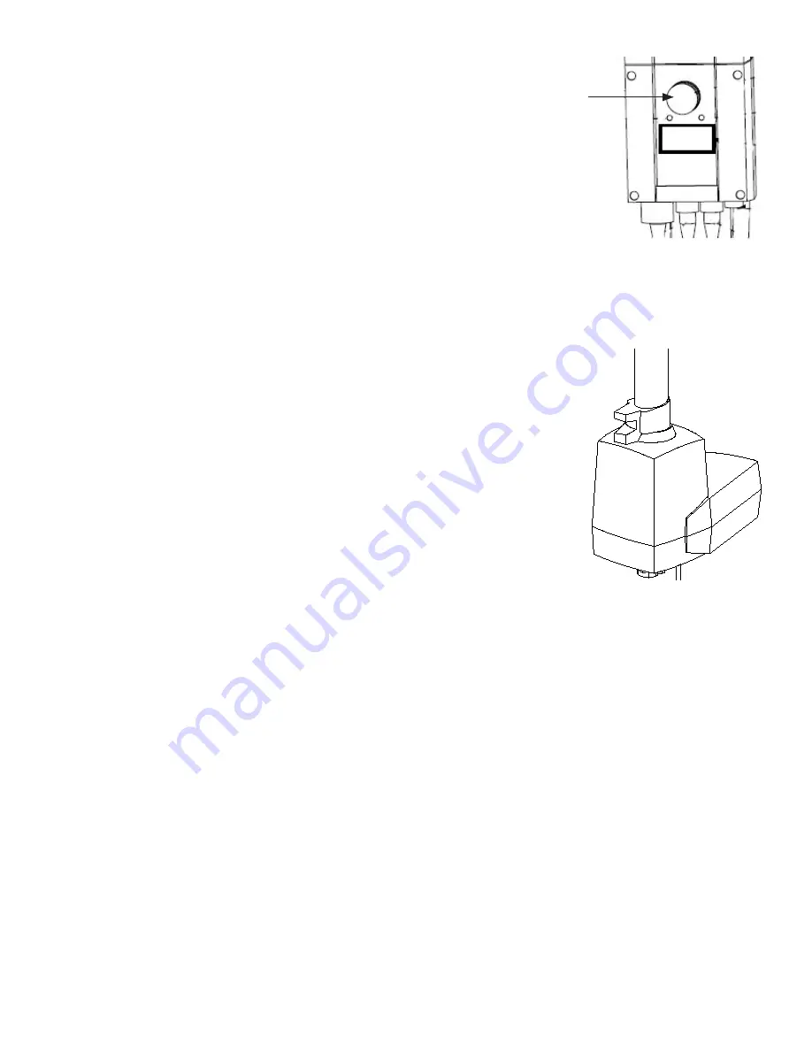
Emergency stop


To activate emergency stop: Depress the red emergency stop 

button on the control box.

Resetting: Turn the button in the direction of the arrows until 

the button pops out.

Emergency lowering

To activate the mechanical lowering function, pull up on the red 

handle.   

Charging

Charge the lifter after each period of daily use so you are always certain the lifter is fully 

operational (e.g. charge it every night).

Charging the MiniLift200:

Plug the mains cable from the control unit into an outlet. When the batteries are 

charged, the charger will turn off automatically.

Remember: The emergency stop button must be disengaged / out.

Battery:

24V DC. 2,9 Ah, IP65. The average battery service life is two years, depending on the 

amount of use. 

11


Содержание MiniLift200

Страница 1: ...age Read instructions for all assistive devices used in connection with transfers Keep the manual where it is accessible to users of the product Do not leave the patient unattended during a lifting situation Checklist before use Make certain the lift is properly assembled Lifting accessories must be properly trial fitted and tested in relation to the patient s needs and functional ability Check Sl...

Страница 2: ...ries 24V DC 2 9 Ah IP65 Charger Built in charger 100 240 VAC 50 60 Hz max 400 mA Motor mast DC24 V 10 5 AH IP54 Operationtime 10 at maximum continous running of 2 minutes Push 7500 N Motor base 24 V DC 12 3 AH IP54 Operationtime 10 at maximum continous opera tion of 2 minutes Push 2000N Material Steel Emergency lowering Mechanical and electrical Castors Back 4 100mm front 3 80mm IP class IP54 A we...

Страница 3: ...ces may max load be exceeded See section on technical infor mation and the product decal on the lift Lifting accessories must be properly trial fitted and tested in relation to the patient s needs and functional ability MiniLift200 may not be charged in wet areas or used during a shower and bath Lift shall not be exposed to running water Do not push Maximum load It may be different maximum allowab...

Страница 4: ...utton control box 9 Knob for adjusting the height and depth of the shin pad unit 10 Manual down button for lowering arm Note the mechanical down button is located on the actuator and is manually operated 11 Electric down button 12 Charging lamp on Fully charged lamp off 13 Stopper for sling loops 14 Lock for adjusting telescope lifting arm in and out 15 Push bar 4 www romedic com 1 2 3 4 5 6 7 8 9...

Страница 5: ...sembly Place the upper section 1 above the lower section 2 and carefully lower it onto the lower section Push all the way down Insert the bolts 3 in all four tubes and tighten Finally place the cap nuts 4 on the bolts Assemble the footplate by attaching it to the crossbar and swinging it down Make sure the pins 6 insert into the holes of the plate Attach the leg spreading cable to the control box ...

Страница 6: ...Measurement MiniLift200 6 www romedic com 1 2 ...

Страница 7: ... distance from wall to CSP at max Height legs spread 860 mm Minimum distance from wall to CSP at max reach legs spread 410 mm K2 Min distance from wall to CSP at min height legs spread 410 mm L Footplate clearance 50 mm M Footplate height 80 mm N Inside space between bars 525 mm O Overall length 1000 mm P Reach from base with legs spread to 700 mm 570 mm R Max reach from base 425 mm Max load 200 k...

Страница 8: ...e MiniLift200 The width of the lower section must be adjusted to achieve the greatest possible stabil ity This is the safest way to move the stand up lifter NOTE A stand up lifter is not a means of transport Turning To turn the stand up lifter stand beside the lifter and grasp the side bar with one hand and the push handle with the other pushing with one hand and pulling with the other Do this at ...

Страница 9: ...ng properly Grasp the handset press the Up button and run the liftarm all the way up Then press the Down button and run the liftarm all the way down Test lift function by lifting a person not a patient using an ap proved sling At the same time check the emergency lowering function with someone on the lift If the equipment is satisfactory upon inspection connect the freestanding adaptor for chargin...

Страница 10: ...th the hand control unit Visual battery indicator Beeper which emits a signal when the batteries need to be charged Plug for hand control unit see drawing Plug for lifting motor see drawing Plug for width adjustment see drawing Control box IP65 To protect the electronic equipment the hand control unit is also furnished with a motor protection switch for the lifting function 10 www romedic com ...

Страница 11: ...handle Charging Charge the lifter after each period of daily use so you are always certain the lifter is fully operational e g charge it every night Charging the MiniLift200 Plug the mains cable from the control unit into an outlet When the batteries are charged the charger will turn off automatically Remember The emergency stop button must be disengaged out Battery 24V DC 2 9 Ah IP65 The average ...

Страница 12: ...ward on the footplate as possible The knee pad unit should be all the way back as a starting point Warning When adjusting the leg width there is a risk of squeezing the user s feet Therefore always make sure to place the user s feet on the footplate Adjust the shin pad unit so that the top of the pad is just below the user s kneecap and at least with enough space to slip a hand between shin and pa...

Страница 13: ... sling straps Push the liftarm back as much as possible and make sure its safely locked Warning Check the lifting arm is locked in position before proceeding with the lift Have the user place his her hands on the lifting arm handle We recommend that the caregiver stand at the side of the user place a hand on the user s shoulder and ask the user to lean back slightly Begin lifting to a stand ing or...

Страница 14: ...e user Lock the wheels on the MiniLift The user shall be guided to lean slightly back while he she is lowered down into sitting position Use the straps at both sides of the sling to guide the user into the right position Pull the liftarm out in it s longest position before removing the loops from the hooks Unlock the buckle and remove the sling 14 www romedic com ...

Страница 15: ...orting we recommend that the emergency stop button be pressed in Store the lift at a temperature exceeding freezing point and at normal relative humidity about 60 Service agreements RoMedic offers the possibility of service agreements for maintenance and regular test ing of your lift Contact your local RoMedic representative Trouble shooting If the lift is not working properly up or down check the...

Страница 16: ...t your RoMedic representa tive for information advice and updates When in doubt contact your RoMedic representative for product trials advice or informa tion If you require additional information contact your transfer specialist or our representative or visit www romedic com Make sure you always have the most recent version of the manual Manuals are available for downloading from our website http ...

Отзывы: