Roland TD-20K Скачать руководство пользователя страница 4


4


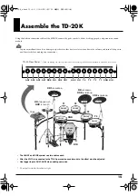
Assemble the Drum Stand.


About the Stand, refer to the MDS-20 Owner’s Manual.

• Do NOT open the legs of the stand more than 135 

degrees. The distance between the back Right/Left end 
legs should NOT be more than 2 m (80 inches), otherwise, 
the cable (inside the Pipes) could be damaged and/or the 
stand could tip over.


fig.01.e


• Do NOT loosen any bolts other than Hand Knobs except 

when changing the parts or cables for repairing.

Attach the stand holder (included with the drum stand MDS-
20) to the TD-20.

Using the screws attached to the bottom panel, attach the 
holder so the unit is oriented as shown in the diagram.


fig.02.e


• To attach the stand holder, remove the four 12 mm 

screws (M5 x 12) from the bottom of the TD-20 and use 
them. Use of other screws may result in damage to the 
unit.


928


• When turning the unit upside-down, get a bunch of 

newspapers or magazines, and place them under the four 
corners or at both ends to prevent damage to the buttons 
and controls. Also, you should try to orient the unit so no 
buttons or controls get damaged.


929


• When turning the unit upside-down, handle with care to 

avoid dropping it, or allowing it to fall or tip over.

Mount the VH-12 on a commercially available hi-hat stand.


Refer to the VH-12 Owner’s Manual.

After the VH-12 is connected to the TD-20 percussion sound 
module, the 


offset


 must be adjusted. For details, read the 

instructions in the TD-20 and VH-12 Owner’s Manuals.


MDS-20 


(Drum Stand)


Caution in Setting Up the Stand

135˚

135˚

2 m


TD-20 


(Percussion Sound Module)


VH-12 


(V-Hi-Hat)

Narrow

Wide

TD-20K_e.book 4 ページ 2006年12月7日 木曜日 午前9時24分

Содержание TD-20K

Страница 1: ... grasp of every feature provided by your new unit Owner s manual should be read in its entirety The manual should be saved and kept on hand as a convenient reference Check the Contents of the Box TD 20 Percussion Sound Module x 1 VH 12 V Hi Hat x 1 KD 120 V Kick Trigger Pad x 1 PD 125 V Pad x 3 PD 105 V Pad x 2 CY 14C V Cymbal Crash x 2 CY 15R V Cymbal Ride x 1 Tuning Key x 1 TD 20K Owner s Manual...

Страница 2: ... supervision until the child is capable of following all the rules essential for the safe operation of the unit 014 Protect the unit from strong impact Do not drop it 104 Try to prevent cords and cables from becoming entangled Also all cords and cables should be placed so they are out of the reach of children 106 Never climb on top of nor place heavy objects on the unit 115b RE Install only the ac...

Страница 3: ...oft dry cloth 402 Never use benzine thinners alcohol or solvents of any kind to avoid the possibility of discoloration and or defor mation Additional Precautions ADD Brushes nylon can be used for brush playing Do NOT use metal brushes 553 Use a reasonable amount of care when using the unit s buttons sliders or other controls and when using its jacks and connectors Rough handling can lead to malfun...

Страница 4: ...rom the bottom of the TD 20 and use them Use of other screws may result in damage to the unit 928 When turning the unit upside down get a bunch of newspapers or magazines and place them under the four corners or at both ends to prevent damage to the buttons and controls Also you should try to orient the unit so no buttons or controls get damaged 929 When turning the unit upside down handle with ca...

Страница 5: ... Use a plastic beater fig 07 e Due to the nature of the materials used in the sensor changes in room temperature and humid may affect the sensitivity of the sensor Contents of the Package Component Parts Names KD 120 Pad Stand Leg x 2 Beater Bracket Lug T bolt Shell Leg Plate Head Hoop Output jack Tuning bolt Lock nut Rubber foot Cushion Sensor TD 20K_e book 5 ページ 2006年12月7日 木曜日 午前9時24分 ...

Страница 6: ...aces When shipped from the factory the stand is adjusted for using the rubber legs If you re using the rubber legs proceed to step 5 on the next page Setup Assembling the KD 120 Output jack Bracket Adjusting for the Spike Legs 1 Loosen the leg nut 2 Turn the rubber foot to adjust so that the spike portion sticks out from the rubber foot Adjust the length of the spike to suit the location where ins...

Страница 7: ...s plate section at a right angle to the floor fig 12 e 11 Make any fine adjustments necessary and tighten the stand brackets to make sure the KD 120 is secure on the stand Make sure the KD 120 s four legs and heel portion of the kick pedal is securely on the floor by loosening the stand s T bolts and adjusting the length of the legs If the kick pedal has no under plate then arrange the stand s pla...

Страница 8: ...ing points of the two beaters fall at equal distances to the left and right of the center of the head fig 13 When using a twin double kick pedal as with a regular pedal use the included beater or a plastic beater as the beater for the kick pedal When Using a Twin Double Kick Pedal TD 20K_e book 8 ページ 2006年12月7日 木曜日 午前9時24分 ...

Страница 9: ...itivity and may even result in incorrect operation Be sure to tighten each tuning bolt a little at a time as described in the above explanation 5 Adjust bolt b so that the tension is the same as the tension of a 6 Next adjust c and d and e and f in the same way 7 Make sure that the head tension is even and repeat steps 5 and 6 if you wish to make further adjustments On the KD 120 adjusting the hea...

Страница 10: ...g it counterclockwise 3 Remove the hoop 4 Remove the old head 5 Place the new head on the shell 6 Place the hoop onto the head 7 First lightly tighten bolt a in the above diagram by rotating it clockwise Then tighten bolt b to about the same force 8 Now lightly tighten c and then d Tighten e and f in the same way 9 Next adjust the tension of the head Refer to Adjusting the Head Tension above Fully...

Страница 11: ...low To prevent malfunction and or damage to speakers or other devices always turn down the volume and turn off the power on all devices before making any connections Rim Shot Capable Trigger Inputs 2 SNARE 3 6 TOM 1 4 12 15 AUX 1 4 Brush Sweep Capable Trigger Inputs 2 SNARE Make sure the snare drum stand you use is designed to firmly hold a 12 inch PD 125 drum Be sure to tighten the stand fixing s...

Страница 12: ...ge over a period of time so readjust when necessary fig 17 e 3 Using the tuning key turn the tuning bolts two full revolutions each thus tightening them Tighten each tuning bolt one by one observing the numerical order shown in the figure fig 18 Adjusting the Head Adjusting the Head Tension Heads MUST BE TUNED BEFORE PLAYING Like with an acoustic drum accurate and equal head tension is needed for ...

Страница 13: ... CY 14C unit Wing nut Wing nut Felt washer Felt washer Stopper Stopper Cable tie Cable tie Component Parts Names Edge Portion Bow Portion Bell Portion BOW BELL OUTPUT Jack BOW EDGE OUTPUT Jack Wing Nut Felt Washer Stopper Edge Portion Bow Portion Wing Nut Felt Washer Stopper BOW EDGE OUTPUT Jack The CY 14C has no BOW BELL OUTPUT Jack TD 20K_e book 13 ページ 2006年12月7日 木曜日 午前9時24分 ...

Страница 14: ... the movement of the cymbal units when struck fig 23 e Take care to ensure that the cables do not touch the cymbal units and or the stand A cable touching a cymbal unit or a stand may cause double sounding or other incorrect operation Double sounding may occur if the wing nut is loose Do NOT use the washer or felt included with the cymbal mount Mounting on the Stand Stopper Be sure to orient it co...

Страница 15: ...nected to the TD 20 percussion sound module the offset must be adjusted Use trigger inputs AUX1 AUX4 when adding new pads Do not pull or stretch the cables too tight T1 T2 T3 T4 PD 125 PD 125 PD 125 RD BOW BELL RDE BOW EDGE CY 14C CY 14C CY 14C CY 14C CY 15R CY 15R CR1 BOW EDGE CR2 BOW EDGE KIK KD 120 SNR PD 105 PD 105 TD 20 HH TRIGGER OUT HHC CTRL OUT VH 12 VH 12 KIK SNR T1 T2 T3 T4 HH HHC CR1 CR...

Страница 16: ...he pad Placing your hand on the head of the pad might prevent the cross stick sound from being played properly With certain snare and tom sounds slight changes in the way you play rim shots changes the nuance fig 27 e Normal Rim Shots Open Rim Shots Strike the head and rim simultaneously fig 29 e Shallow Rim Shots Simultaneously strike the head near the rim and the rim itself The same effect is pr...

Страница 17: ...f the stick On the CY 14C bell shots are not supported fig 33 e Choke Play Choking pinching the cymbal s edge with the hand immediately after hitting the cymbal makes the sound stop Choke the location of the edge sensor shown in the figure If you choke an area where there is no sensor the sound does not stop fig 34 The CY 15R is capable of sensing the point on the bow that is struck You need to ch...

Страница 18: ...er portion is one component that eventually wears out the more so if numerous rim shots are performed and will require replacement Rim shots may not be performed correctly when the rubber portion is worn out If this occurs replace the hoop Consult Roland Service for more on replacing the hoop Size 15 inches Triggers 3 Bow Bell Edge Connectors BOW BELL Output Jack BOW EDGE Output Jack Dimensions 37...

Страница 19: ...19 Specifications This product complies with the requirements of European Directive 89 336 EEC For EU Countries TD 20K_e book 19 ページ 2006年12月7日 木曜日 午前9時24分 ...

Страница 20: ...duvira Asuncion PARAGUAY TEL 595 21 492147 PERU Audionet Distribuciones Musicales SAC Juan Fanning 530 Miraflores Lima Peru TEL 511 4461388 TRINIDAD AMR Ltd Ground Floor Maritime Plaza Barataria Trinidad W I TEL 868 638 6385 NORWAY Roland Scandinavia Avd Kontor Norge Lilleakerveien 2 Postboks 95 Lilleaker N 0216 Oslo NORWAY TEL 2273 0074 POLAND ROLAND POLSKA SP Z O O UL Gibraltarska 4 PL 03 664 Wa...

Отзывы: