19
Sep. 2012
INTEGRA-7
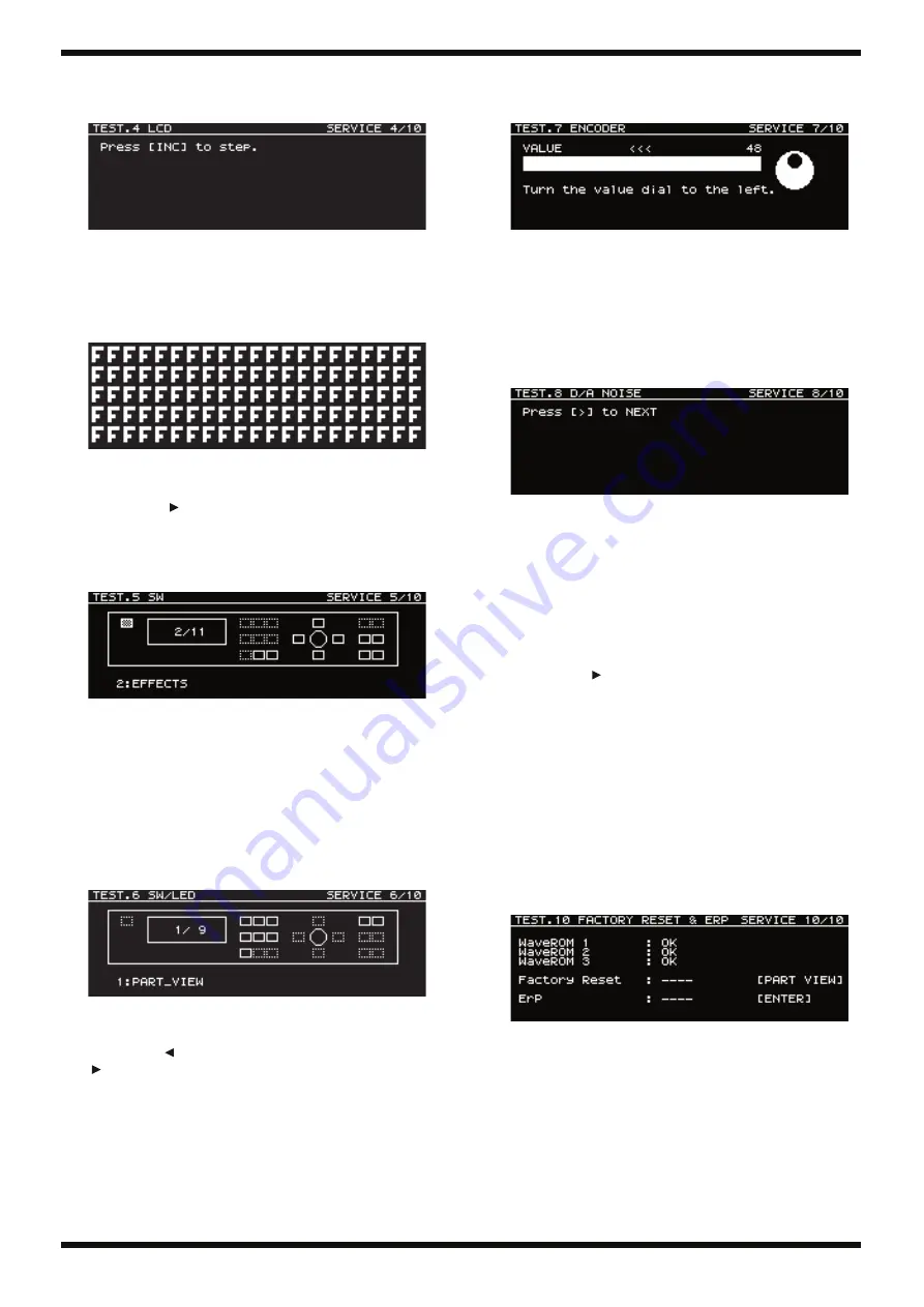
4. LCD Screen
This verifies the display of the LCD screen.
fig.screen004.eps
1.
Press
INC
to display each screen in succession.
2.
Verify that each screen is free of dot drop-out, uneven color, grime,
soiling, and scratching.
3.
Turn the encoder clockwise and counterclockwise, and verify that the
contrast changes.
fig.screen005.eps
4.
Press
INC
several more times, and verify that the screen luminance
(brightness) changes.
5.
Press
CURSOR
to advance to the next test item.
5. SW
This verifies the operation of switches that have no LEDs.
fig.screen006.eps
1.
Working in sequence, press the buttons indicated on-screen.
* The button on the left side of the screen indicates the
VOLUME
control
PREVIEW
button.
When you have finished pressing all buttons, execution automatically
advances to the next test item.
6. SW/LED
This verifies the operation of LED-equipped switches.
fig.screen007.eps
1.
Working in sequence, press the buttons indicated on-screen, and verify
that the LED for each goes dark.
* Pressing
PART
makes the
MIDI
LED (green) go dark, and pressing
PART
makes the
USB
LED (yellow) go dark.
When you have finished pressing all buttons, execution automatically
advances to the next test item.
7. ENCODER
This verifies the operation of the encoder.
fig.screen008.eps
1.
Turn the encoder counterclockwise 2 turns, and verify that
0
is displayed.
2.
In the same way, turn the control clockwise 2 turns.
The value
48
is displayed, and execution automatically advances to the
next test item.
8. D/A NOISE
This measures residual noise.
fig.screen009.eps
1.
Adjust
VOLUME
to
MAX
.
2.
Connect the noise meter to
OUTPUT A L/MONO
and
R
(TRS), and verify
that the values shown below are obtained.
L:
-86 dBm
or lower (DIN audio or JIS A)
R:
-86 dBm
or lower (DIN audio or JIS A)
3.
Connect the noise meter to
OUTPUT B L
and
R
(TRS), and verify that the
values shown below are obtained.
L:
-86 dBm
or lower (DIN audio or JIS A)
R:
-86 dBm
or lower (DIN audio or JIS A)
Press
CURSOR
to advance to the next test item.
9. SHOCK TEST
1.
Connect headphones, press the
PREVIEW (PUSH)
button, and verify the
sound.
2.
Lift the front of the unit 5 centimeters, then let it fall. (Do this 3 times.)
3.
Verify that when impact is applied, no sound drop-out or momentary
power interruption (restart) occurs.
10. FACTORY RESET & ERP
This verifies the results of the wave ROM check, carries out a factory
reset, and verifies ERP operation.
fig.screen010.eps
1.
Verify that
OK
is displayed for all items from
WaveROM 1
through
3
.
If
Busy
is displayed, wait until
OK
is displayed. (This can take up to
around 2 minutes.)
* The check of the entire wave ROM region starts after
been executed. If
DEVICE 2
has been skipped, the message
Busy
remains
displayed without change.
2.
Press
PART VIEW
, and verify that the message
Factory Reset : OK
is
displayed.
* The message
Busy
is displayed for several seconds until
OK
appears.
Содержание INTEGRA-7 SuperNATURAL
Страница 8: ...8 Sep 2012 INTEGRA 7 Plane View 1 fig bunkaizu H1 eps a a a f f a d b c d b View 1 View 3 View 2...
Страница 10: ...10 Sep 2012 INTEGRA 7 Plane View 2 fig bunkaizu H2 eps e h e e g d e i e e View 4 View 5 View 6 View 7...
Страница 13: ...13 Sep 2012 INTEGRA 7 fig block eps R...
Страница 21: ...21 Sep 2012 INTEGRA 7...
Страница 22: ...22 Sep 2012 INTEGRA 7 Circuit Board Main Board fig b main1 eps...
Страница 23: ...23 Sep 2012 INTEGRA 7 fig b main2 eps...
Страница 34: ...34 Sep 2012 INTEGRA 7 Circuit Board Sub Panel Jack VR ENC Inlet Front Jack SW Board fig b SUB1 eps...
Страница 35: ...35 Sep 2012 INTEGRA 7 fig b SUB2 eps...


