Roland GI-20 Скачать руководство пользователя страница 57

57

Installing & Setting Up the Driver (Windows)

Settings

MIDI input and output destinations

Windows XP/2000/Me users

1.

Open “Control Panel.”

Click the Windows Start button, and from the menu that appears, select “Settings | Control Panel.” 

Windows XP

Click the Windows start button, and from the menu that appears, select “Control Panel.” 

2.

Open the “Sounds and Audio Devices Properties” dialog box (or in Windows 
2000/Me, Sounds and Multimedia Properties).

Windows XP

1) In “Pick a category”, click “Sound, Speech, and Audio Devices”. 

2) Next, in “or pick a Control Panel icon”, click the “sounds and Audio Devices” icon.

Windows 2000/Me

1) In Control Panel, double-click the “Sounds and Multimedia” icon to open the “Sounds and 

Multimedia Properties” dialog box.

3.

Click the Audio tab.
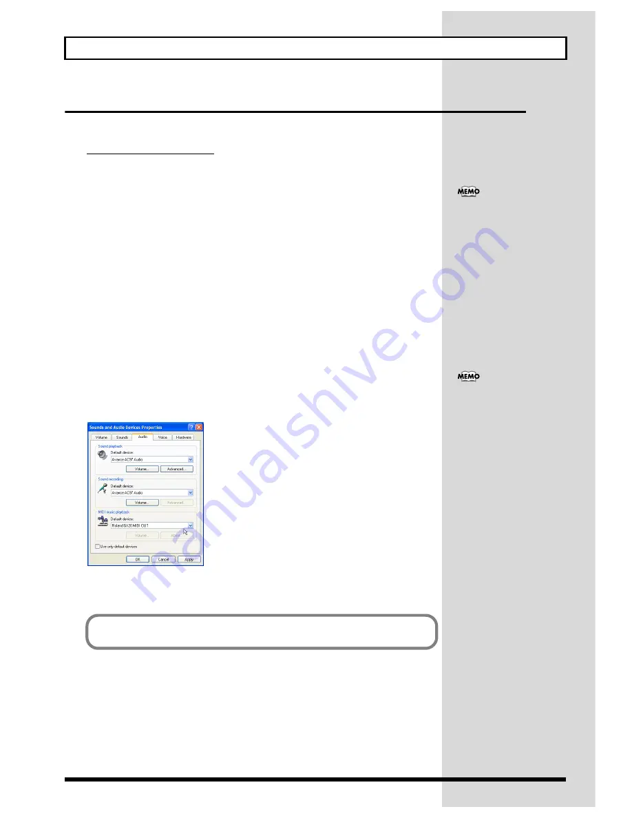
4.

For MIDI music playback, click the 

 located at the right of [Default device] (or 

in Windows 2000/Me, [Preferred device]), and select the following from the list 
that appears.

Roland GI-20 MIDI OUT

fig.d28

5.

Click [OK] to close the “Sounds and Audio Devices Properties” dialog box. 

Depending on how your 
system is set up, the “Sounds 
and Audio Devices” icon may 
be displayed directly in the 
Control Panel (the Classic 
display). In this case, double-
click the “Sounds and Audio 
Devices” icon.

If the “Sound and Multimedia” 
icon is not displayed, click 
“Show all control panel 
options” in the frame at the 
left.

This completes driver settings.

Содержание GI-20

Страница 1: ...or connect it to a computer and use it as an input tool for sequencers or similar applications Compatible with guitars and basses Features internal patch memory allowing you to store a variety of dif...

Страница 2: ...utlet and request servicing by your retailer the nearest Roland Service Center or an authorized Roland distributor as listed on the Information page when The AC adaptor or the power supply cord has be...

Страница 3: ...er The resulting sound may be of a level that could cause permanent hearing loss Damage to speakers or other system components may result 101b The unit and the AC adaptor should be located so their lo...

Страница 4: ...horoughly with a soft dry cloth 402 Never use benzine thinners alcohol or solvents of any kind to avoid the possibility of discoloration and or deformation Additional Precautions 553 Use a reasonable...

Страница 5: ...itch of the Sound TRANSPOSE 23 Setting the Range in Which Pitches Are Changed BEND RANGE 23 Switching Sounds on External Devices PRG CHANGE 25 Muting Specific Strings STRING MUTE 26 Storing the Settin...

Страница 6: ...ng the sensitivity this indicates the level 4 WRITE button Use this for writing patches Write procedure p 26 This is also used as the button to execute Factory Reset p 34 and Bulk Dump p 29 5 SELECT E...

Страница 7: ...you are using Switch to GUITAR if you are using a guitar if using a bass switch this to BASS Note that the GI 20 may not operate properly if this setting is not correct 13 FOOT SW jack Connect an opt...

Страница 8: ...8 Panel Descriptions Signal Flow fig 00 04 Guitar Bass Foot Switch Expression Pedal...

Страница 9: ...rd that enables electronic instruments and peripherals to share information about performances sound switching and other functions MIDI is a standard that is shared by a wide range of instruments from...

Страница 10: ...status of the GUITAR BASS switch This does not appear in the display when the GUITAR BASS switch setting is changed at a later point fig 00 12 With the factory settings all of the GI 20 s patch settin...

Страница 11: ...on the MIDI sound module and monitor speakers or other device 2 Turn off the power to the power amp or other device 3 Turn off the power to the MIDI sound module and the GI 20 Adjusting the Input Sen...

Страница 12: ...s values for the parameters described below and switching these patches allows you to reproduce their settings instantly fig 01 06 System Parameters and Patch Parameters In contrast to the patch param...

Страница 13: ...in Play mode When switching patches turn the PARAMETER knob to return to Play mode GM General MIDI is a set of recommended standards covering the way sounds are played by MIDI sound module the arrange...

Страница 14: ...se function normally when you play notes individually 1 Turn the PARAMETER knob to MIDI CHANNEL fig 01 10 2 Press SELECT to select MONO POLY When MONO POLY is selected only the leftmost indicator ligh...

Страница 15: ...o the same number MIDI messages transmitted over other channels are disregarded However when the control channel is set to OMNI mode Omni MIDI messages are received regardless of the channel With the...

Страница 16: ...l number If you want to set the omni mode select oM fig 01 17 4 When you have finished making the settings turn the PARAMETER knob to return to PLAY MODE The Control channel is a system parameter It i...

Страница 17: ...he GI 20 from your computer Input here is performance data from guitars and basses equipped with GK connectors Roland GI 20 MIDI OUT This is the port used for outputting performance data to your compu...

Страница 18: ...ilar instruments the vibrating strings are touched directly giving the player the ability to exert subtle control over the dynamics To realize most faithfully this aspect of the guitar you need to set...

Страница 19: ...hus the standard set ting for play Fi Finger picking The setting for when you want to per form with the feeling finger picking provides Sensitivity is a little higher than Normal Hd Hard picking This...

Страница 20: ...erefore if the same assign settings are used for both of the patches prior to and following the switch the status of the controllers is carried over However if the assign settings are different for th...

Страница 21: ...nds from the same string simultaneously H2 GR Hold 2 The sound being played is held the moment you press the foot switch and continues to be held while you hold the pedal down The synth sound is not p...

Страница 22: ...5 u8 Glide Up 5 8 d5 d8 Glide Down 5 8 When the foot switch is pressed the pitch changes continuously up down to one octave Release the pedal to re turn to the original pitch The higher the numeral se...

Страница 23: ...tinuous pitch changes obtained with techniques such as bending finger vibrato tremolo bar usage and sliding to an external device This is done using MIDI Pitch Bend Change messages Setting Bend Range...

Страница 24: ...nge When the Chromatics C1 C3 are selected if you use string bending or other techniques that bend the guitar or bass pitch the changes in pitch transmitted in the MIDI mes sages are made in semitone...

Страница 25: ...44 3 If you want to change the string settings press TUNER STRING SEL to select the string numbers The string number changes each time you press TUNER STRING cycling through ALL 1 2 3 4 5 6 ALL fig 0...

Страница 26: ...Write procedure to save the settings to a patch Switching patches p 13 or turning off the power without first carrying out the Write procedure will cause the created settings to be deleted System par...

Страница 27: ...o PLAY MODE 2 Select the copy source patch refer to How to Switch Patches on p 13 3 Press WRITE The display flashes fig 02 50 4 Press PATCH VALUE to select the copy destination patch To cancel the Cop...

Страница 28: ...factory The reference pitch is a system parameter It is saved automatically when the TUNER is turned off even without the Write procedure being carried out and the settings values are applied to all...

Страница 29: ...nsferred in and out of the GI 20 using MIDI or USB You can also save patches externally to equipment that can record MIDI data For this kind of operation the GI 20 uses MIDI messages called System Exc...

Страница 30: ...will result in the loss of the data stored up to that time 1 Connect the external device s MIDI OUT to the MIDI IN on the GI 20 2 Turn the PARAMETER knob to BULK fig 03 06 3 Press SELECT to select LM...

Страница 31: ...ing the Size of a MIDI Pitch Bend Message BEND DATA THIN The Bend Data Thin Function With the guitar the finger vibrato technique can be used to produce organic vibratos with amplitude and speed that...

Страница 32: ...urn the power off Limiting the Extent of the Bend Range BEND RANGE MAX Although the GI 20 has a maximum bend range setting of 24 unless the GI 20 and your sound module feature the same bend range sett...

Страница 33: ...to the GI 20 2 Hold down WRITE and turn on the power 3 Press SELECT causing only the leftmost indicator of the display to light up Only the leftmost indicator light when you select USB DRIVER TYPE fig...

Страница 34: ...mp operation p 29 to save them before performing the Factory Reset operation 1 Turn off the power to the GI 20 2 Set GUITAR BASS to match the instrument you are using guitar or bass 3 Hold down TUNER...

Страница 35: ...ND RANGE p 23 set to anything other than 24 With BEND RANGE MAX set to anything other than 24 if Glide Up Down 5 8 or Pitch Bend 3 or 6 is used in Assign p 19 then changing the pitch by an octave caus...

Страница 36: ...ontrol Change value transmitted with the previous patch Therefore if the same assign settings are used for both of the patches prior to and following the switch the status of the controllers is carrie...

Страница 37: ...ed processing due to an attempt to transmit numerous MIDI messages from the GI 20 at one time The GI 20 s MIDI IN OUT connectors may be connected with a single MIDI cable Action 1 Check the connection...

Страница 38: ...way transfer and handshake transfer One way transfer procedure See Section 3 for details This procedure is suited to the transfer of a small amount of data It sends out an Exclusive message completely...

Страница 39: ...mpatibility with such devices Roland has limited the DT1 to 256 bytes so that an excessively long message is sent out in separate segments A DT1 message is capable of providing only the valid data amo...

Страница 40: ...the GI 20 Does not convert to basic channel for transmission General Purpose Controller 5 Status 2nd byte 3rd byte BnH 50H vvH n MIDI channel number 0H FH 0 15 0 ch 1 15 ch 16 vv Control value 00H 7FH...

Страница 41: ...1 15 ch 16 mm Upper byte of the parameter data designated by RPN ll Lower byte of the parameter data designated by RPN RPN Control change includes RPN registered parameter number function which are d...

Страница 42: ...and their hexadecimal counterparts 10 16 10 16 10 16 10 16 0 00H 32 20H 64 40H 96 60H 1 01H 33 21H 65 41H 97 61H 2 02H 34 22H 66 42H 98 62H 3 03H 35 23H 67 43H 99 63H 4 04H 36 24H 68 44H 100 64H 5 05...

Страница 43: ...fter powering off 2 O X is selectable 3 Can be assigned the Expression Pedal Foot Switch 1 2 and GK Volume 4 Can be received when Bulk Load is standby Model GI 20 Date Dec 26 2002 Version 1 00 MIDI Im...

Страница 44: ...H inches Weight 1 3 kg 2 lbs 14 oz excluding AC adaptor Accessories AC Adaptor 120 230 V ACI series 230 UK 240 V ACB series GK Cable 3 m MIDI Cable 1 m Owner s Manual CD ROM USB driver Rubber Foot x...

Страница 45: ...that is running on the USB connected computer The GI 20 Driver sends data from the application to the GI 20 and passes data from the GI 20 to the application The explanation about installing and setu...

Страница 46: ...note of the current setting Warn or Block Then change the setting to Ignore and click OK The installation procedure will differ depending on your system Please proceed to one of the following section...

Страница 47: ...the GI 20 to your computer 1 With the power switch turned OFF connect the AC adaptor to the GI 20 2 Connect the AC adaptor to an electrical outlet 3 Use the USB cable to connect the GI 20 to your com...

Страница 48: ...he Model field indicates Roland GI 20 and click Next Driver installation will begin If the What action do you want Windows to take setting was not set to Ignore a Hardware Installation dialog box will...

Страница 49: ...rent for your system Specify the drive name of your CD ROM drive The Found New Hardware Wizard will appear fig d11 17 Make sure that the display indicates Roland GI 20 and click Finish Wait until Foun...

Страница 50: ...m the menu select Control Panel 3 In Pick a category click Performance and Maintenance 4 In or pick a Control Panel icon click the System icon The System Properties dialog box will appear Depending on...

Страница 51: ...ure that File signature verification is set to Ignore If it is set to Ignore simply click OK If it is not set to Ignore make a note of the current setting Warn or Block Then change the setting to Igno...

Страница 52: ...ower switch turned OFF connect the AC adaptor to the GI 20 2 Connect the AC adaptor to an electrical outlet 3 Use the USB cable to connect the GI 20 to your computer fig d99 12 Switch ON the GI 20 s p...

Страница 53: ...Roland GI 20 is displayed and click Finish fig d20 If the File signature verification setting was not set to Ignore a Digital Signature Not Found dialog box will appear If File signature verification...

Страница 54: ...Windows restarts 1 After Windows restarts log in to Windows as a user with administrative privileges such as Administrator 2 In the Windows desktop right click the My Computer icon and from the menu...

Страница 55: ...r computer 4 Click the Windows Start button From the menu that appears select Run fig d22 Open the Run dialog box fig d23 5 In the dialog box that appears input the following into the Open field and c...

Страница 56: ...fy the drive name of your CD ROM drive Once the driver has been installed New Hardware Found dialog box will close 9 In the SetupInf dialog box click OK The SETUPINF dialog box will close Next you nee...

Страница 57: ...s icon Windows 2000 Me 1 In Control Panel double click the Sounds and Multimedia icon to open the Sounds and Multimedia Properties dialog box 3 Click the Audio tab 4 For MIDI music playback click the...

Страница 58: ...pen the Multimedia Properties dialog box In Control Panel double click the Multimedia icon to open the Multimedia Properties dialog box 3 Click the MIDI tab fig d28 4 Set MIDI output Select Single ins...

Страница 59: ...e numerous other variables that can affect performance including differences in hardware design system configuration and overall combination of software applications that are used Therefore the actual...

Страница 60: ...procedure 1 Connect the GI 20 to your computer 1 With the power switch turned OFF connect the AC adaptor to the GI 20 2 Connect the AC adaptor to an electrical outlet 3 Use the USB cable to connect t...

Страница 61: ...box and click OK fig d37 7 After making sure that the Roland GI 20 is listed in the OMS MIDI Device Setup dialog box click check box to check mark and click OK fig d38 8 The Save dialog box will appea...

Страница 62: ...d40 13 In the My Studio Setup Window click the keyboard icon When you move the mouse cursor near the keyboard icon the cursor will change to the shape of an eighth note Verify that you can hear sound...

Страница 63: ...to FreeMIDI dialog box will appear Click Continue If this is the second or later time select FreeMIDI Preferences from the File menu 4 In the FreeMIDI Preferences dialog box check GI 20 Port which is...

Страница 64: ...priate model does not appear in the list select Other Studio Location Select GI 20 7 When settings are complete click Done A setting window like the following will appear fig d47 8 If you selected Oth...

Страница 65: ...B audio device driver installed in your computer and then re install the GI 20 driver as described in Installing setting Up the Driver Windows p 46 Also check whether there is any Other devices in Dev...

Страница 66: ...hat the computer has detected the GI 20 incorrectly As described in Deleting incorrect device information delete the incorrect device information then re install the driver Installing Setting Up the D...

Страница 67: ...log box Did you make Driver Signing Options In order to install re install the driver you must make the settings described in Driver Signing Options Windows XP p 46 Windows 2000 p 51 Deleting the driv...

Страница 68: ...k Hide file extensions for known file types and check Show all files in Hidden files Then click the OK button For Windows Me 1 Open the Control Panel and double click Folder Options Then click View ta...

Страница 69: ...ITAR SEL 11 13 18 GUITAR BASS 7 10 34 H Hold 21 I Indicator 12 Input Sensitivity 11 18 L LOAD MIDI 30 LOAD USB 31 M MASTER TUNE 12 28 MIDI 7 9 MIDI BASIC CH 12 MIDI CHANNEL 14 MIDI Channel 14 MIDI CTL...

Страница 70: ...3 26 STRING SEL 6 System Exclusive 9 System Parameter 12 T Transmission Mode 14 20 22 23 25 32 TRANSPOSE 13 23 Tuner 6 26 28 TUNER STRING SEL 23 25 26 28 34 Tuner Indicator 6 Tuning 28 U USB 7 10 17 3...

Страница 71: ...ons However there is no guarantee that interference will not occur in a particular installation If this equipment does cause harmful interference to radio or television reception which can be determin...

Страница 72: ...Diagorou Street Nicosia CYPRUS TEL 022 66 9426 DENMARK Roland Scandinavia A S Nordhavnsvej 7 Postbox 880 DK 2100 Copenhagen DENMARK TEL 3916 6200 FRANCE Roland France SA 4 Rue Paul Henri SPAAK Parc de...

Отзывы: