background image

1

Programmable thermostat

EASY SETUP GUIDE

ST.2

EN

INTRODUCTION

This thermostat is designed to aid in the comfort of your home by providing timed 
regulation of your heating system. The thermostat is designed to receive temperature 
input signals from the following sensors:

1. Air sensor located inside thermostat.

2. Floor sensor installed in floor (see heater instructions for details).

The thermostat is not a safety device and should only be used with Rointe heating 
products. In order to avoid damaging your flooring the correct floor type must be selected  
during the thermostat programming process.

WARNING - Important safety note

This product uses mains voltage electricity and work should only be carried out by a 
qualified electrician. You should always isolate the power supply before attempting 
to install or repair the thermostat. The thermostat should not be put into operation 
unless you are certain that the entire heating installation complies with current general 
requirements for electrical installations. Electrical installation must be in accordance with 
the latest wiring regulations.

LOCATION

The thermostat should be installed inside a single electrical wall box that is at least 35mm 
deep. For optimal performance the thermostat should be located in an area with good 
ventilation. It should not be beside a window/door, in direct sunlight or above heat 
generating device (e.g. radiator or TV). The thermostat is designed for operation between 
0ºC and 55ºC with relative humidity less than 80%.

INSTALLATION

Separate the front housing of thermostat from wall module:

1. Unscrew both closing screws (bottom of thermostat) until they will not turn any
further.

2. Release front housing by gripping lower half of outer frame and pulling outwards.

3. Place front housing somewhere safe.

4. Run all wires to the wall box. Check to ensure that you have included the following:

Power (Live and Neutral)

Heater (Live and Neutral or Switch Live only)

Floor sensor

5. Pull wires through wall box and complete terminal wiring.

IMPORTANT: 

Ensure that multi stranded wires are fully inserted into the terminals and 

secured tightly. Any loose strands should be trimmed as they could cause a short-circuit. If 
connecting more than two heaters, an electricial junction box will be required.

Note: 

Always ensure that the sensor cable is installed in a separate conduit to the power 

supplying the thermostat and heating system.

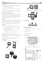
MOUNTING STEPS

1. Release the front cover by inserting a screwdriver into bottom crack.

2. Take the backing plate apart according to the following diagram.

3. Mount the backing plate on the wall socket using a screwdriver.

4. After connecting the wires (see connection diagram), mount the 

thermostat to the backplate and remount the cover and frame.

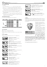
CONNECTION DIAGRAM

ELECTRICAL SPECIFICATION

•  Supply voltage: 230V +/- 10% at 50Hz

•  Thermostat is not designed for use with intermittent power supply.

•  Maximum Switch Load: 16A resistive

•  Insulation Class: II

•  IP20

•  Standards: EN60730-1 & EN60730-2-9

DISPLAY SYMBOLS

DIMENSIONS

Содержание ST.2

Страница 1: ...r TV The thermostat is designed for operation between 0ºC and 55ºC with relative humidity less than 80 INSTALLATION Separate the front housing of thermostat from wall module 1 Unscrew both closing screws bottom of thermostat until they will not turn any further 2 Release front housing by gripping lower half of outer frame and pulling outwards 3 Place front housing somewhere safe 4 Run all wires to...

Страница 2: ...electric systems For Rointe electric systems please skip this step 7RLE Potential free output and main power output in same different way Press or key to change the present linkage state 00 in same way 01 in different way Press key to enter to next step Not applicable to electric systems For Rointe electric systems please skip this step 8DLY Delay time of potential free output Press or key to chan...

Страница 3: ...stato está diseñado para operar entre 0ºC y 55ºC con una humerdad relativa inferior al 80 INSTALACIÓN Separe la carcasa frontal del termostato del módulo de pared 1 Afloje los tornillos de cierre parte inferior del termostato hasta que no giren 2 Suelte la carcasa frontal tirando hacia fuera de la mitad inferior del marco exterior 3 Coloque la carcasa frontal en un lugar seguro 4 Pase todos los ca...

Страница 4: ... Presione para ir al siguiente paso No aplicable a sistemas eléctricos Para los sistemas eléctricos Rointe omita este paso 7RLE Salida sin potencial y salida principal de la misma diferente manera Presione o para cambiar valor actual 00 de la misma manera 01 de diferente manera Presione para ir al siguiente paso No aplicable a sistemas eléctricos Para los sistemas eléctricos Rointe omita este paso...

Страница 5: ... Le thermostat est conçu pour fonctionner entre 0ºC et 55ºC avec une humidité relative inférieure à 80 INSTALLATION Séparer le boîtier frontal du thermostat du module mural 1 Desserrer les vis partie inférieure du thermostat jusqu à ce qu ils ne tournent plus 2 Déverrouiller le boîtier frontal en tirant sur la moitié inférieure du cadre extérieur 3 Placez le boîtier frontal dans un endroit sûr 4 P...

Страница 6: ... pas aux systèmes électriques Pour les systèmes électriques Rointe ignorez cette étape 7RLE Sortie libre de potentiel et sortie principale de la même manière différente Appuyez sur ou pour modifier la valeur actuelle 00 de la même manière 01 d une manière différente Appuyer sur pour passer à l étape suivante Ne s applique pas aux systèmes électriques Pour les systèmes électriques Rointe ignorez ce...

Страница 7: ... com umidade relativa menor que 80 INSTALAÇÂO Separe a tampa frontal do termostato do módulo de parede 1 Solte os parafusos de travamento parte inferior do termostato até que nâo roden 2 Solte a tampa de frente puxando para fora da mitade inferior do quadro externo 3 Coloque a tampa da frente em um local seguro 4 Passar todos os fios para a caixa de parede Certifique se de ter inclído o seguinte A...

Страница 8: ...mas eléctricos Para os sistemas eléctricos da Rointe pule esta etapa 7RLE Saida sem potencial e saida principal da mesma maneira diferente Pressione ou para alterar o valor atual 00 da mesma maneira 01 diferente Pressione para ir o próximo passo Nâo aplicavel a sistemas eléctricos Para os sistemas eléctricos da Rointe pule esta etapa 8DLY Tempo de atraso na saida sem potencial Pressione ou para al...

Отзывы: