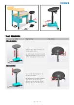
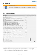
background image

162 / 207   - NL - 

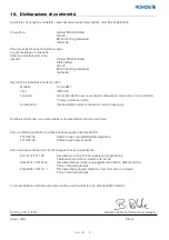
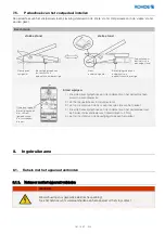
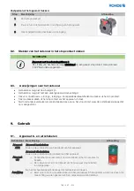
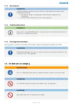
Netsnoer met het apparaat verbinden: 

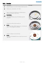
Netsnoer uit het apparaat trekken: 

Stap 

Beschrijving 

Afbeelding 

Zet het apparaat uit. 

Trek de stekker van het netsnoer uit het stopcontact. 

Druk het grijze lipje aan de rechthoekige ingang van het apparaat 
voorzichtig met een schroevendraaier omhoog. 

Trek tegelijkertijd de stekker uit de ingang. 

8.1.2.

Voetpedaal met het apparaat verbinden 

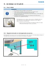
AANWIJZING 

Om de pottenbakkersdraaischijf te kunnen gebruiken, moet de klinkstekker van het voetpedaal 
in het apparaat zijn gestoken en het voetpedaal worden bediend. 

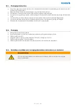
Voetpedaal met het apparaat verbinden: 

Aan de onderzijde van het apparaat zit de 
rechthoekige ingang voor het netsnoer. Steek 
de rechthoekige stekker van het netsnoer in 
de ingang tot hij vastklikt. De rechthoekige 
stekker past slechts op één manier in de 
ingang. 

Aan de onderzijde van het apparaat zit de 
ronde ingang voor de kabel van het 
voetpedaal. Steek de klinkstekker van het 
voetpedaal in de ingang tot hij vastklikt. 

Содержание HMT 600

Страница 1: ...ctions Pottery Wheel HMT 600 Manuel d utilisation original Tour de potier HMT 600 Manual de instrucciones original Torno HMT 600 Istruzioni per l uso originali Tornio HMT 600 Originele gebruiksaanwijzing Pottenbakkersdraaischijf HMT 600 Původní návod k provozu Hrnčířský kruh HMT 600 ...

Страница 2: ...ferscheibe HMT 600 ab Seite 3 English Original Operating Instructions Pottery Wheel HMT 600 1 from page 31 Français Manuel d utilisation original tour de potier HMT 600 2 de la page 59 Español Manual de instrucciones original el torno HMT 600 3 de la página 89 Italiano Istruzioni per l uso originali tornio HMT 600 4 da pagina 119 Nederlands Originele gebruiksaanwijzing pottenbakkersdraaischijf HMT...

Страница 3: ...anwendungen 10 5 Kurzanleitung 10 6 Anlieferung 11 6 1 Lieferung prüfen 11 6 2 Gerät auspacken 11 6 3 Verpackung entsorgen 11 7 Aufstellung Montage 11 7 1 Hinweise zum Aufstellort 11 7 2 Gerät transportieren 11 7 3 Optionales Zubehör zusammenbauen montieren 12 7 3 1 Ablage zusammenbauen am Gerät montieren optionales Zubehör 12 7 3 2 Sitz zusammenbauen optionales Zubehör 13 7 3 3 Sitz am Gerät mont...

Страница 4: ...gsintervalle 23 11 2 Antrieb 23 11 3 Werkskundendienst 23 11 4 Wartungsvertrag 24 11 5 Ersatzteile 24 12 Pflege Reinigung 24 12 1 Pflegehinweise 24 12 2 Reinigung 25 12 3 Scheibenkopf Spritzschutzwanne zur Reinigung demontieren montieren 25 12 3 1 Demontage 25 12 3 2 Montage 26 13 Störung 27 14 Entsorgung 28 15 Zusätzliche Informationen 28 15 1 Hinweis zur Haftung 28 15 2 Gewährleistungsbestimmung...

Страница 5: ...uf in Spritzschutzwanne 1 Stück 5 Werkzeug Innensechskantschlüssel 3mm 5mm 8mm je 1 Stück 6 Mitnehmer Schrauben für Holzplatte 2 Stück Holzplatte separat erhältlich 7 Betriebsanleitung 1 Stück Optional erhältlich 1 Sitz zerlegt in Sitzfläche Gasdruckfeder und Sitzfuß 1 Stück Artikel Nr 550601 2 Ablage mit Streben und Anbaumaterial zerlegt 1 Stück Artikel Nr 550602 3 Holzplatte 1 Stück Artikel Nr 6...

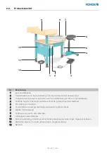
Страница 6: ...los längsverstellbar und werkzeuglos von der Töpferscheibe trennbar 5 Ablaufschlauch aus Spritzschutzwanne 6 Komfort Sitz gepolstert sowie in Höhe und Neigung einstellbar 7 Spritzschutzwanne demontierbar 8 Scheibenkopf mit Indexierung demontierbar 9 Ablage demontierbar 10 Motor und Antrieb wartungsarm und vor Umwelteinflüssen im Gehäuse geschützt 11 Gerätefüße stufenlos und werkzeuglos höhenverste...

Страница 7: ... der Beschreibung von potenziell gefährlichen Arbeitsschritten aufgeführt 3 1 2 Arten aufgeführter sicherheitsbezogener Hinweise GEFAHR Das Symbol mit Signalwort bezeichnet eine unmittelbar drohende Gefahr Wenn sie nicht gemieden wird sind Tod oder schwerste Verletzungen die Folge WARNUNG Das Symbol mit Signalwort bezeichnet eine möglicherweise drohende Gefahr Wenn sie nicht gemieden wird können T...

Страница 8: ... WARNUNG Aus Sicherheitsgründen muss vor Wartungs Störungsbehebungs Reinigungs und Instandsetzungsarbeiten der Netzstecker aus der Steckdose gezogen werden WARNUNG Geräte Abdeckung nicht öffnen Im Gehäuse befinden sich keine Teile die vom Benutzer zu warten sind VORSICHT Verletzungsgefahr Warnung vor rotierenden Bauteilen VORSICHT Der Transport und die Montage der Töpferscheibe sollten auf Grund d...

Страница 9: ... Reparatur und Wartungsarbeiten an elektrischen Bauteilen dürfen nur durch eine Elektrofachkraft durchgeführt werden 3 4 Hinweis zur Anleitung Lesen Sie die Anleitung vollständig durch bevor Sie die Töpferscheibe in Betrieb nehmen Bewahren Sie diese Anleitung sorgfältig auf Die in dieser Anleitung abgebildeten Darstellungen dienen zur Erklärung der Funktionen und können teilweise vom tatsächlichen...

Страница 10: ...r Reinigungsmittel Einsatz zu Schulungs und Ausbildungszwecken ohne dauerhafte und ausreichende Aufsicht durch unterwiesenes und qualifiziertes Personal Einsatz in Betreuungseinrichtungen für Kinder Jugendliche oder behinderte Menschen ohne dauerhafte und ausreichende Aufsicht durch unterwiesenes und qualifiziertes Personal Das Netzkabel wird mit einem Verlängerungskabel verlängert Das Gerät wird ...

Страница 11: ...Sie von Ihrem Händler oder der Gemeinde bzw Stadtverwaltung 7 Aufstellung Montage 7 1 Hinweise zum Aufstellort Stellen Sie die Töpferscheibe auf eine ebene Fläche Eventuelle Unebenheiten des Bodens können durch die in der Höhe anpassbaren Kunststofffüße ausgeglichen werden Das mitgelieferte Netzkabel direkt in die nächstmögliche Steckdose stecken Das Netzkabel ist lang genug bemessen und darf nich...

Страница 12: ...e 2 Gewindestangen von Hand in das Gerät eindrehen im Uhrzeigersinn Überstand auf der Arbeitsplatte 21cm 3 2 Stück der unteren Stützscheiben platzieren Wölbung nach oben ausrichten 4 Die 2 Hohlstreben und die 2 oberen Stützscheiben platzieren Wölbung nach unten ausrichten 5 Die Ablage aufsetzen und die 2 Schraubenmuttern einschrauben Werkzeug Innensechskantschlüssel 5 mm im Lieferumfang der Töpfer...

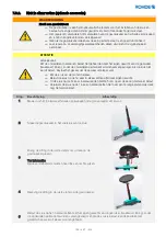
Страница 13: ...es wieder voneinander lösen Den Sitz am Boden zusammenbauen Nach dem 1 Zusammenbau unbedingt durch Eigengewicht belasten Nach dem 1 Zusammenbau und ohne Belastung nicht übermäßig heben Nach dem 1 Zusammenbau und ohne Belastung nicht über weite Distanzen tragen Schritt Beschreibung Abbildung 1 Achten Sie beim Zusammenbau darauf dass alle Oberflächen trocken fettfrei und frei von Verschmutzungen sin...

Страница 14: ...e Kreuzlibelle ausgerichtet werden Dazu können die Kunststofffüße heraus oder hineingeschraubt werden Zum Ausrichten sollte die Wasserwaage stets nur auf den Scheibenkopfe aufgelegt werden Beim Ausrichten ist der Einsatz des optionalen Sitzes zu beachten Der sitzseitige Gerätefuß muss dann weniger aus dem Fußrohr herausgeschraubt werden Der Sitz wird unter den Fuß der Töpferscheibe gesteckt Der Fu...

Страница 15: ...inkel an der Unterseite des Pedals mit einem Schraubendreher Kreuzschlitz wieder anbringen Drehmoment 4 Nm 5 Achten Sie auf die Position des Befestigungswinkels am Pedalkörper 8 Inbetriebnahme 8 1 Verkabelung am Gerät montieren 8 1 1 Netzkabel am Gerät montieren GEFAHR Warnung vor gefährlicher elektrischer Spannung Ziehen Sie den Stecker des Netzkabels vor Arbeiten am Gerät aus der Steckdose Nase ...

Страница 16: ...Töpferscheibe muss der Klinkenstecker des Fußpedals am Gerät eingesteckt sein und das Fußpedal betätigt werden Fußpedal mit dem Gerät verbinden An der Unterseite der Töpferscheibe befindet sich die eckige Buchse zum Einstecken des Netzkabels Das Netzkabel muss mit dem eckigen Stecker in die Buchse eingesteckt werden bis er einrastet Der eckige Stecker passt nur in einer bestimmten Position in die ...

Страница 17: ...en aus der Steckdose ziehen Den Netzstecker nur bei ausgeschaltetem Gerät aus der Steckdose ziehen Niemals weitere Verbraucher mittels Mehrfach Steckerleiste an die Steckdose anschließen an welcher die Töpferscheibe angeschlossen ist 9 Betrieb 9 1 Gerät ein ausschalten Schalter Beschreibung Abbildung Gerät AN Gerät einschalten Grüne Taste seitlich am Gerät drücken Gerät AUS Gerät ausschalten Rote ...

Страница 18: ...al in Position AUS stellen und den Stillstand der Drehscheibe abwarten 2 Den Kippschalter auf Position 0 stellen 3 Den Kippschalter in die jeweils andere Richtung stellen 9 3 Fußpedal bedienen Bedienung des Fußpedals Position am Fußpedal Aktion an der Töpferscheibe Pedal in Position 0 Ruheposition keine Drehzahl Stillstand Pedal in Position Maximal maximal mögliche Drehzahl Pedal in beliebiger Pos...

Страница 19: ...richtung und Ausstattung des Aufstellraumes durch ausgelaufenes Material 10 2 Magnethalter für mitgeliefertes Zubehör Das mitgelieferte Zubehör in Form der 3 Innensechskantschlüssel und der 2 Mitnehmer Schrauben für Holzplatten kann an den Magnetstreifen innen am unteren Gehäuse positioniert werden Der mitgelieferte Stöpsel ist mit einem Überlauf versehen D h das Material kann bei eingesetztem Stö...

Страница 20: ...ung der Töpferscheibe 10 4 2 Längsverstellung des Sitzes Der Sitz kann durch Lösen des Hebelspanners längs zur Töpferscheibe stufenlos verstellt werden Dazu muss die Spannschraube gegen den Uhrzeigersinn gelöst werden und der Sitzfuß herausgezogen oder eingeschoben werden Anschließend muss die Spannschraube im Uhrzeigersinn wieder festgezogen werden Der Hebel der Spannschraube kann durch Anheben i...

Страница 21: ...n die Sitzhöhe eingestellt werden Durch Belasten der Sitzfläche wird die Sitzhöhe abgesenkt und durch Entlasten wird die Sitzhöhe vergrößert Sitzneigung einstellen Durch Ziehen des linken Hebels kann die Sitzneigung eingestellt werden Durch Belasten der Sitzfläche wird die Sitz Vorderkante abgesenkt und durch Entlasten angehoben ...

Страница 22: ...opf zu schrauben Dazu muss allerdings der Scheibenkopf gelöst und abgenommen werden siehe Abschnitt 12 3 Das hat aber den Vorteil dass sich der Innensechskant der Gewindestifte beim Töpfern nicht mit Ton zusetzt Werkzeug Innensechskantschlüssel 3 mm im Lieferumfang der Töpferscheibe enthalten mit Mitnehmer Die Gewindestifte müssen durch die Mitnehmer Schrauben im Lieferumfang enthalten ersetzt wer...

Страница 23: ...on und Wasser X Prüfung der optionalen Mitnehmer Schrauben für die Holzplatten auf feste Verschraubungen X Sichtprüfung des Sitzes falls vorhanden insbesondere auf feste Verbindung von Sitz Gasdruckfeder und Sitzfuß X Sichtprüfung der Ablage falls vorhanden insbesondere auf feste Verschraubung am Gerät X Reinigung des Geräts insbesondere Ton und Wasser aus der Spritzschutzwanne entfernen X Fußpeda...

Страница 24: ...in die Elektrik oder den Antrieb gelangt Dies kann das Gerät beschädigen Die Spritzschutzwanne sollte nach jedem Drehvorgang entleert werden und darf nicht überlaufen Die Spritzschutzwanne besitzt eine Anlaufkante und kann so gut gereinigt werden Ist der Ton schon angetrocknet kann man diesen wieder einweichen und nach kurzer Zeit leicht mit einem Tuch oder Lappen entfernen Der Inhalt der Spritzsc...

Страница 25: ...ontage oder Montage den Netzstecker aus der Steckdose ziehen und Reste von Ton und Wasser entfernen 12 3 1 Demontage Schritt Beschreibung Abbildung 1 Gerät ausschalten und den Netzstecker aus der Steckdose ziehen 2 Reste von Ton und Wasser aus der Spritzschutzwanne entfernen 3 Die Schraube in der Mitte des Scheibenkopfs gegen den Uhrzeigersinn lösen und entfernen Werkzeug Innensechskantschlüssel 8...

Страница 26: ...r die Bohrung in der Arbeitsplatte positioniert werden Der Schlauch darf nicht geknickt werden 3 Den Scheibenkopf aufsetzen Achtung Achten Sie darauf dass der Scheibenkopf ohne Kraftaufwand oder Verkanten auf den Aufnahmebolzen aufgesetzt werden kann Achten Sie darauf dass die Mitnehmer am Gerät genau in die Aussparungen des Scheibenkopfs passen 4 Die Schraube in der Mitte einsetzen und festziehen...

Страница 27: ...enstecker des Fußpedals am Gerät einstecken Kippschalter für die Drehrichtung steht in der Neutralstellung Mit dem Kippschalter die jeweilige Drehrichtung wählen Fußpedal nicht betätigt Fußpedal betätigen Das Gerät wurde vorher im laufenden Betrieb mit der roten Taste ausgeschaltet und mit der grünen Taste wieder eingeschaltet Siehe Abschnitt 10 2 Motor Antrieb oder Lagerung defekt oder verschliss...

Страница 28: ... umgehend Mängel Defekte oder Störungen die die Sicherheit beeinträchtigen können Angaben zur Sicherheit können nicht gegen den Hersteller ausgelegt werden Selbst wenn alle Sicherheits und Warnhinweise die Originalbetriebsanleitung und mitgeltende Dokumente befolgt werden ist nicht gewährleistet dass das Gerät keine Verletzungen oder Schäden verursacht Der Hersteller übernimmt keinerlei Haftung fü...

Страница 29: ...ngsausschluss Beim Inhalt dieser Originalbetriebsanleitung kann es zu Abweichungen kommen welche der technischen Änderung zu schulden sind Die Angaben in diesem Dokument werden regelmäßig überprüft notwendige Korrekturen sind in den nachfolgenden Auflagen enthalten Dieses Dokument unterliegt nicht dem automatischen Änderungsdienst Die Wiedergabe von Gebrauchsnamen Handelsnamen oder Warenbezeichnun...

Страница 30: ...attet Ferner wird erklärt dass die speziellen technischen Unterlagen erstellt wurden Die Schutzziele der folgenden weiteren EU Richtlinien werden erfüllt 2014 30 EU Richtlinie über elektromagnetische Verträglichkeit 2014 35 EU Niederspannungsrichtlinie Folgende harmonisierte Normen wurden unter Anderem angewandt DIN EN ISO 12100 2011 03 Sicherheit von Maschinen allgemeine Gestaltungsleitsätze Risi...

Страница 31: ...9 6 2 Unpacking the machine 39 6 3 Disposal of packaging 39 7 Installation assembly 39 7 1 Notes on the operating location 39 7 2 Transporting the machine 39 7 3 Assembling mounting optional accessories 40 7 3 1 Assembling the shelf mounting it on the machine optional accessory 40 7 3 2 Assembling the seat optional accessory 41 7 3 3 Mounting the seat on the machine 42 7 4 Adjusting the machine at...

Страница 32: ... 11 Maintenance 51 11 1 Maintenance intervals 51 11 2 Drive 51 11 3 Customer service 51 11 4 Maintenance contract 52 11 5 Spare parts 52 12 Care cleaning 52 12 1 Care instructions 52 12 2 Cleaning 53 12 3 Disassembling reassembling the wheel head splash pan for cleaning 53 12 3 1 Disassembly 53 12 3 2 Assembly 54 13 Faults 55 14 Disposal 56 15 Additional Information 56 15 1 Notice of liability 56 ...

Страница 33: ...mm 5 mm 8 mm Allen keys 1 of each 6 Drive screws for wooden throwing batt 2 Wooden throwing batt sold separately 7 Operating manual 1 Optional 1 Seat disassembled into seat gas pressure spring and seat base 1 Item no 550601 2 Tray with struts and mounting materials disassembled 1 Item no 550602 3 Wooden throwing batt 1 Item no 657052 2 Product description 2 1 General technical characteristics Prop...

Страница 34: ...base continuously adjustable lengthways and can be separated from the pottery wheel without tools 5 Drain hose from splash pan 6 Comfort seat upholstered and adjustable for height and inclination 7 Splash pan detachable 8 Wheel head with indexing detachable 9 Shelf detachable 10 Motor and drive low maintenance and protected from environmental influences in housing 11 Machine feet continuously heig...

Страница 35: ...ese original operating instructions before the description of potentially dangerous work steps 3 1 2 Types of listed safety related notices DANGER A symbol with the signal word indicates imminent danger If it is not avoided death or severe injuries will result WARNING A symbol with the signal word indicates possible impending danger If it is not avoided death or severe injuries can result CAUTION ...

Страница 36: ...ified personnel WARNING For safety reasons the power plug must be removed from the socket before maintenance troubleshooting cleaning and repair work WARNING Do not open the machine cover There are no user serviceable parts inside CAUTION Risk of rotating parts causing physical injury CAUTION The transport and assembly of the pottery wheel should be carried out by at least 2 people due to its heav...

Страница 37: ... and water from the wooden surfaces Repair and maintenance work on electrical components may only be carried out by a qualified electrician 3 4 Note on instructions Read the instructions completely before using the pottery wheel Please keep these instructions in a safe place The illustrations shown in these instructions illustrate the functions and may differ in some ways from the actual product 4...

Страница 38: ...ained and qualified personnel Use in care facilities for children adolescents or disabled people without permanent and adequate supervision by trained and qualified staff Extending the power cable with an extension cable Using the machine as a step or climbing aid Placing objects of any kind everything except ceramic clay on the turntable and putting the machine into operation 5 Quick start guide ...

Страница 39: ...he disposal of packaging material please contact your local specialist community council or municipal administration 7 Installation assembly 7 1 Notes on the operating location Place the pottery wheel on a flat surface Any unevenness in the floor can be compensated for using height adjustable plastic feet Plug the supplied power cord directly into the nearest possible socket The power cable is lon...

Страница 40: ...on Store the screws in a safe place 2 Screw the 2 threaded rods into the machine by hand clockwise Protrusion above the worktop 21 cm 3 Position 2 of the lower support washers align the curvature upwards 4 Position the 2 hollow struts and the 2 upper support washers align the curvature downwards 5 Place the shelf on top and screw in the 2 nuts Tool 5 mm Allen key included in the pottery wheel s sc...

Страница 41: ...at the parts of the seat will separate from each other again Assemble the seat on the floor After the 1st assembly you must load it with your own weight Do not lift unduly after the 1st assembly and without any load After the first assembly and without load do not carry it over long distances Step Description Illustration 1 When assembling make sure that all surfaces are dry and free of grease and...

Страница 42: ...rit level or a two axis spirit level at right angles The plastic feet can be screwed in or out to achieve this For alignment the spirit level should only be placed on the wheel head When aligning the use of the optional seat must be taken into account The machine foot at the seat then has to be unscrewed less from the foot tube than the other two The seat is inserted under the foot of the pottery ...

Страница 43: ...mounting angle on the underside of the pedal with a Phillips screwdriver torque 4 Nm 5 Pay attention to the position of the mounting angle on the pedal body 8 Installation 8 1 Installing the wiring on the machine 8 1 1 Installing the power cable on the machine DANGER Danger high voltage Before working on the machine pull the power plug out of the socket Lug in upper detent Mounting angle attached ...

Страница 44: ...erate the pottery wheel the jack plug of the foot pedal must be plugged into the machine and then pressed Connecting the foot pedal to the machine The square socket for plugging in the power cord is located on the underside of the pottery wheel The square plug on the power cord must be plugged into the socket until it clicks into place The square plug only fits into the socket in one certain posit...

Страница 45: ...ork Only pull the power plug out of the socket when the machine is switched off Never connect additional loads to the socket to which the pottery wheel is connected using a power strip 9 Operation 9 1 Switching the machine on off Switch Description Illustration Machine ON Switching the machine on Press the green button on the side of the machine Machine OFF Switching off the machine Press the red ...

Страница 46: ...n 1 Put the foot pedal in the OFF position and wait for the turntable to stop 2 Set the selector switch to position 0 3 Set the selector switch to the other direction 9 3 Operating the foot pedal Operation of the foot pedal Position on the foot pedal Action at the pottery wheel Pedal in position 0 rest position No rotation standstill Pedal at maximum position Maximum possible speed Pedal in any po...

Страница 47: ...ishings and equipment in the installation room due to material that has leaked 10 2 Magnetic holder for the supplied accessories The supplied accessories like the 3 Allen keys and the 2 drive screws for a wooden throwing batt can be positioned on the magnetic strips on the inside of the lower housing The stopper supplied has an overflow I e the material can rise to a certain point in the splash pa...

Страница 48: ...on 10 4 Adjusting the ergonomics 10 4 1 Adjusting the height of the pottery wheel 10 4 2 Adjusting the seat longitudinally The distance of the seat from the pottery wheel can be continuously adjusted by loosening the lever clamp To do this the tensioning screw must be loosened anticlockwise and the seat base pulled out or pushed in Then the clamping screw must be tightened again in a clockwise dir...

Страница 49: ...n be adjusted by pulling the right lever The seat height is lowered by loading the seat and the seat height is increased by relieving the load Adjusting the seat inclination The seat angle can be adjusted by pulling the left lever The front edge of the seat is lowered by loading the seat and raised by relieving it ...

Страница 50: ...the wheel head from below To do this however the wheel head must be loosened and removed see Section 12 3 This has the advantage though that the hexagon socket of the grub screws does not become clogged with clay during pottery Tool 3 mm Allen key included in the pottery wheel s scope of delivery With carriers The grub screws must be replaced by the drive screws included in the scope of delivery T...

Страница 51: ...ts especially due to clay and water X Check the optional drive screws for the wooden throwing batts for tight screw connections X Visual inspection of the seat if available in particular that the seat gas pressure spring and seat base are firmly connected X Visual inspection of the shelf if fitted in particular checking that it is securely screwed to the machine X Clean the machine especially remo...

Страница 52: ...r water overflows and gets into the electrical system or the motor This can damage the machine The splash pan should be emptied after each throwing process and must not overflow The splash pan has a rim and can be cleaned easily If the clay is already dry you can soak it again and after a short time remove it easily with a cloth or rag The contents of the splash pan can be emptied into a bucket th...

Страница 53: ... power plug out of the socket and remove any residues of clay and water 12 3 1 Disassembly Step Description Illustration 1 Switch off the machine and pull the power plug out of the socket 2 Remove residues of clay and water from the splash pan 3 Turn the screw in the centre of the wheel head anticlockwise to loosen and remove it Tool 8 mm Allen key included in the pottery wheel s scope of delivery...

Страница 54: ...drain hose must be positioned centrally over the hole in the worktop The hose must not be kinked 3 Put on the wheel head Attention Make sure that the wheel head can be placed on the locating bolt without any effort or tilting Make sure that the carriers on the machine fit exactly into the recesses in the wheel head 4 Insert and tighten the screw in the centre Tool 8 mm Allen key included in the po...

Страница 55: ... plug of the foot pedal into the machine The selector switch for the direction of rotation is in the neutral position Select the desired direction of rotation with the selector switch Foot pedal has not been pressed Operate the foot pedal The machine was previously switched off during operation with the red button and switched on again with the green button See Section 10 2 Motor drive or bearing ...

Страница 56: ... against the manufacturer Even if all safety and warning signs the original operating instructions and other applicable documents are followed there is no guarantee that the machine will not cause injuries or damage The manufacturer assumes no liability for personal injury property damage and damage to the product as well as any consequential damage that arises or has arisen from non compliance wi...

Страница 57: ...echnical changes The information in this document is checked regularly necessary corrections are included in the subsequent editions This document is not subject to the automatic update service Common names trade names or product names are reproduced without special identification as these are generally known However these names and designations could be the property of companies or institutes 15 ...

Страница 58: ...equipped with a seat and or shelf We also declare that the special technical documents have been created The protection goals of the following additional EU directives have been met 2014 30 EU Electromagnetic Compatibility Directive 2014 35 EU Low Voltage Directive The following harmonised standards were used among others EN 12100 2011 03 Safety of machinery General principles for design Risk asse...

Страница 59: ... 67 6 1 Contrôle de la marchandise livrée 67 6 2 Déballage de l appareil 67 6 3 Élimination de l emballage 67 7 Mise en place et montage 67 7 1 Indications relatives au lieu d installation 67 7 2 Transport de l appareil 67 7 3 Assemblage et montage des accessoires en option 68 7 3 1 Assemblage de la tablette accessoire en option et montage sur l appareil 68 7 3 2 Assemblage du siège accessoire en ...

Страница 60: ...1 2 Entraînement 79 11 3 Service après vente usine 80 11 4 Contrat de maintenance 80 11 5 Pièces de rechange 80 12 Entretien et nettoyage 80 12 1 Instructions d entretien 81 12 2 Nettoyage 81 12 3 Démontage et remontage de la girelle et du bac pour le nettoyage 81 12 3 1 Démontage 82 12 3 2 Montage 83 13 Dérangement 84 14 Élimination 85 15 Informations supplémentaires 85 15 1 Indication relative à...

Страница 61: ...é 5 Outil clé à six pans creux de 3 5 et 8 mm 1 de chaque 6 Vis à bout téton pour rondeau 2 unités Rondeau disponible séparément 7 Manuel d utilisation 1 unité Disponible en option 1 Siège livré démonté assise pied vérin à gaz 1 unité N d article 550601 2 Tablette avec supports et matériel de montage à monter 1 unité N d article 550602 3 Rondeau 1 unité N d article 657052 2 Description du produit ...

Страница 62: ...réglable en continu dans le sens de la longueur détachable du tour sans outil 5 Tuyau d écoulement du bac 6 Siège confort rembourré hauteur et inclinaison réglables 7 Bac de protection contre les projections démontable 8 Girelle à indexage démontable 9 Tablette démontable 10 Moteur et entraînement requérant peu d entretien et protégés sous carter contre les influences extérieures 11 Pieds de l app...

Страница 63: ...iption d étapes de travail potentiellement dangereuses 3 1 2 Différents types de consignes de sécurité répertoriées DANGER Ce symbole avec mot de signalisation désigne un danger imminent Si on ne prend aucune mesure pour l éviter il entraînera la mort ou des blessures très graves AVERTISSEMENT Ce symbole avec mot de signalisation désigne un danger potentiel Si on ne prend aucune mesure pour l évit...

Страница 64: ...SEMENT Pour des raisons de sécurité il faut retirer la fiche secteur de la prise avant tous travaux de maintenance dépannage nettoyage et remise en état AVERTISSEMENT Ne pas ouvrir le couvercle de l appareil Le carter ne contient aucune pièce requérant un entretien par l utilisateur PRUDENCE Risque de blessures Attention composants en rotation PRUDENCE En raison du poids élevé du tour de potier il...

Страница 65: ...n électricien qualifié sera autorisé à effectuer les travaux de réparation et de maintenance sur les composants électriques 3 4 Remarque concernant le manuel Veuillez lire intégralement le manuel avant de mettre le tour en service Conservez soigneusement ce manuel Les photos représentées dans ce manuel servent à expliquer les fonctions elles peuvent différer en partie du produit réel 4 Utilisation...

Страница 66: ... suffisante par un personnel formé et qualifié L utilisation dans des structures d accueil pour enfants adolescents ou personnes handicapées sans surveillance permanente et suffisante par un personnel formé et qualifié Le câble d alimentation est rallongé avec un câble de rallonge L appareil est utilisé comme marchepied ou comme escabeau Des objets de toutes sortes quels qu ils soient hormis les a...

Страница 67: ...s veuillez vous adresser à votre revendeur ou aux services administratifs de votre commune ou de votre ville 7 Mise en place et montage 7 1 Indications relatives au lieu d installation Placez le tour sur une surface plane On peut régler la hauteur des pieds en plastique pour compenser d éventuelles inégalités du sol La fiche du câble d alimentation fourni doit être branchée directement dans la pri...

Страница 68: ...e 2 Visser les 2 tiges filetées à la main dans l appareil dans le sens horaire Elles dépassent de 21 cm du plan de travail 3 Disposer 2 rondelles d appui en bas tourner le renflement vers le haut 4 Mettre en place les 2 supports creux et poser 2 rondelles d appui dessus tourner le renflement vers le bas 5 Poser la tablette et visser les 2 écrous Outillage clé à six pans creux de 5 mm comprise dans...

Страница 69: ...olidariser Assembler le siège au sol Après le 1er assemblage appliquer impérativement le poids propre de l utilisateur sur le siège Après le 1er assemblage ne pas soulever le siège outre mesure si on ne lui a pas encore appliqué de charge Après le 1er assemblage ne pas porter le siège sur de grandes distances si on ne lui a pas encore appliqué de charge Étape Description Figure 1 À l assemblage ve...

Страница 70: ...allation en s aidant d un niveau à bulle ou d un niveau à bulle en croix Pour ce faire on peut visser ou dévisser les pieds en plastique Il est recommandé de toujours poser le niveau à bulle sur la girelle Pour mettre le tour de niveau tenir compte du siège éventuellement mis en œuvre Dans ce cas le pied de l appareil côté siège doit être moins dévissé hors du tube de piétement Le siège s emboîte ...

Страница 71: ...de la pédale couple 4 Nm 5 Faites attention à la position de l équerre de fixation sur le corps de la pédale 8 Mise en service 8 1 Brancher les câbles sur l appareil 8 1 1 Brancher le câble d alimentation sur l appareil DANGER Mise en garde tension électrique dangereuse Avant tous travaux sur l appareil débrancher la fiche du câble d alimentation de la prise Ergot en haut dans le dispositif d arrê...

Страница 72: ...le tour il faut que la fiche jack du câble de la pédale soit branchée sur l appareil et il faut actionner la pédale Relier la pédale à l appareil Sur la face inférieure du tour de potier se trouve une prise rectangulaire pour brancher le connecteur du câble d alimentation Il faut enfoncer le connecteur rectangulaire du câble d alimentation dans la prise jusqu à ce qu il s enclenche Le connecteur r...

Страница 73: ...age nettoyage et remise en état Retirer la fiche secteur de la prise uniquement lorsque l appareil est arrêté Ne jamais raccorder d autres consommateurs via multiprise à la prise à laquelle le tour de potier est branché 9 Fonctionnement 9 1 Mise en marche et arrêt de l appareil Interrupteur Description Figure Appareil MARCHE Mettre l appareil en marche Appuyer sur le bouton vert sur le côté de l a...

Страница 74: ...1 Mettre la pédale en position ARRÊT et attendre que le plateau tournant s immobilise 2 Mettre l interrupteur à bascule sur la position 0 3 Mettre l interrupteur à bascule sur la position correspondant à l autre sens de rotation 9 3 Actionnement de la pédale Utilisation de la pédale Position de la pédale Effet sur le tour Pédale en position 0 position de repos Aucune vitesse de rotation arrêt Péda...

Страница 75: ... responsabilité pour les dommages causés à l aménagement et l équipement du local d installation par un écoulement du matériau 10 2 Support magnétique pour les accessoires fournis Les accessoires fournis sous forme de 3 clé à six pans creux et de 2 Vis à bout téton pour rondeau peuvent être positionnés sur la bande magnétique à l intérieur du boîtier inférieur Le bouchon fourni est pourvu d un tro...

Страница 76: ... Réglage de la hauteur du tour 10 4 2 Réglage du siège dans le sens de la longueur En desserrant le dispositif de serrage à levier on peut régler le siège en continu dans le sens de la longueur par rapport au tour À cet effet il faut desserrer la vis de serrage dans le sens antihoraire puis tirer le piétement du siège vers l extérieur ou l enfoncer plus avant Il faut ensuite resserrer la vis de se...

Страница 77: ...baisser la hauteur de l assise cette dernière augmentant en revanche au fur et à mesure qu on diminue la pression exercée sur le siège Réglage de l inclinaison du siège On peut régler l inclinaison de l assise en tirant sur le levier gauche En s asseyant alors sur le siège on abaisse le bord antérieur de l assise ce dernier se relevant en revanche au fur et à mesure qu on diminue la pression exerc...

Страница 78: ...elle À cet effet il faut toutefois dévisser et déposer la girelle voir section 12 3 Mais cela présente l avantage que l embout à six pans creux des vis sans tête ne se remplira pas d argile pendant le tournage Outillage clé à six pans creux de 3 mm comprise dans le matériel fourni avec le tour avec tétons d entraînement Il faut remplacer les vis sans tête par les vis à bout téton comprises dans le...

Страница 79: ...urfaces en bois pour déceler d éventuels dommages dus notamment à l eau et à l argile X Contrôle visuel des rondeaux mis en œuvre en option pour déceler d éventuels dommages et défauts dus notamment à l eau et à l argile X Contrôle du vissage solide des vis à bout téton optionnelles permettant l utilisation de rondeaux X Contrôle visuel du siège suivant équipement notamment de la solidité de l ass...

Страница 80: ...RTISSEMENT Pour des raisons de sécurité il faut retirer la fiche secteur de la prise avant tous travaux de nettoyage NOTA Le tour ne doit pas être aspergé d eau pour le nettoyage NOTA Il est recommandé de soumettre le tour une fois par an à un contrôle et une maintenance par le service après vente usine Cette maintenance périodique assurée par le service après vente usine est vivement recommandée ...

Страница 81: ...yclé ensuite Pour un nettoyage approfondi on peut démonter le plateau tournant en aluminium ainsi que le bac Enlever immédiatement les restes d eau et d argile des surfaces en bois 12 2 Nettoyage Nettoyez l appareil après chaque utilisation Ne jamais asperger l appareil avec un jet d eau un tuyau d eau ou un nettoyeur haute pression Ne pas utiliser d air comprimé Éliminer l eau l argile et les aut...

Страница 82: ...girelle en la tournant dans le sens antihoraire puis la retirer Outillage clé à six pans creux de 8 mm comprise dans le matériel fourni avec le tour 4 Déposer la girelle en la soulevant dans l axe Attention Évitez d endommager la girelle en la heurtant ou en la faisant tomber 5 Déposer le bac en le soulevant dans l axe Attention Le bac est fixé au plateau de bois avec du Velcro le bac y adhère sol...

Страница 83: ...é centré au dessus de l orifice ménagé dans le plan de travail Il ne faut pas plier ni couder le tuyau 3 Mettre la girelle en place Attention Veillez à ce que la girelle puisse être posée sur le boulon de réception sans la coincer en travers ni forcer Veillez à ce que les tétons d entraînement de l appareil s insèrent exactement dans les orifices de la girelle 4 Mettre la vis en place au centre et...

Страница 84: ... électrique de l immeuble Contrôler le panneau électrique de l immeuble et les fusibles On peut mettre l appareil en marche mais la girelle ne tourne pas La fiche jack de la pédale n est pas branchée sur l appareil Brancher la fiche jack de la pédale sur l appareil L interrupteur à bascule pour le sens de rotation est en position neutre Choisir le sens de rotation voulu avec l interrupteur à bascu...

Страница 85: ...échets usuels ou les ordures ménagères Pour subir un traitement approprié les appareils électriques doivent être collectés et éliminés séparément De cette manière vous contribuez à la récupération au recyclage et à la réutilisation de matières premières Afin de protéger l environnement les composants et emballages utilisés sont pour la plupart faciles à éliminer Respectez les lois réglementations ...

Страница 86: ...t les pièces de rechange d origine du fabricant Aucune modification ne doit être effectuée sur le tour de potier Si en raison de modifications non autorisées des dommages surviennent sur l appareil et d autres biens matériels ou si des personnes subissent des dommages corporels de ce fait aucune prétention à dommages et intérêts ne pourra être revendiquée auprès du fabricant 15 2 Conditions de gar...

Страница 87: ...ns légales Droits d auteur Helmut ROHDE GmbH Reproduction interdite La traduction la réimpression et la reproduction même partielle ne sont autorisées qu avec l accord écrit de la société Helmut ROHDE GmbH Service de modifications Sous réserve de modifications liées à des perfectionnements techniques Ce manuel d utilisation original n est pas soumis au service de modifications automatique 15 6 Con...

Страница 88: ...tablette Nous déclarons en outre que la documentation technique spécifique a été établie Les objectifs de protection des autres directives de l UE reprises ci dessous sont remplis 2014 30 UE Directive relative à la compatibilité électromagnétique 2014 35 UE Directive basse tension Les normes harmonisées suivantes ont notamment été appliquées EN 12100 2011 03 Sécurité des machines Principes générau...

Страница 89: ...obar el volumen de entrega 97 6 2 Desembalaje del equipo 97 6 3 Cómo desechar el embalaje 97 7 Instalación y montaje 97 7 1 Notas sobre el lugar de instalación 97 7 2 Transporte del equipo 97 7 3 Ensamblaje y montaje de los accesorios opcionales 98 7 3 1 Ensamblaje y montaje del estante en el equipo accesorio opcional 98 7 3 2 Montaje del asiento accesorio opcional 99 7 3 3 Montaje del asiento en ...

Страница 90: ...to 109 11 3 Servicio técnico de fábrica 110 11 4 Contrato de mantenimiento 110 11 5 Recambios 110 12 Conservación y limpieza 110 12 1 Instrucciones de conservación 111 12 2 Limpieza 111 12 3 Desmontar y montar el plato y la cubeta protectora para su limpieza 111 12 3 1 Desmontaje 112 12 3 2 Montaje 113 13 Avería 114 14 Eliminación de residuos 115 15 Otra información 115 15 1 Nota sobre la responsa...

Страница 91: ... cada 6 Tornillos para los arrastradores del plato de madera 2 unidades El plato de madera se vende por separado 7 Manual de instrucciones 1 unidad Opcional 1 Asiento compuesto por superficie del asiento amortiguador de gas a presión y pie del asiento 1 unidad N º ref 550601 2 Estante con puntales y material de montaje desmontado 1 unidad N º ref 550602 3 Plato de madera 1 unidad N º ref 657052 2 ...

Страница 92: ...uo se puede separar del torno sin necesidad de herramientas 5 Tubo de desagüe de la cubeta protectora 6 Asiento confortable acolchado y ajustable en altura e inclinación 7 Cubeta protectora desmontable 8 Cabezal de plato ranurado desmontable 9 Estante desmontable 10 Motor y accionamiento de bajo mantenimiento y protegidos de las influencias ambientales por la carcasa 11 Patas del equipo con altura...

Страница 93: ...con los trabajos y las señales de obligación aparecen siempre antes de describir cada paso de trabajo potencialmente peligroso 3 1 2 Tipos de indicaciones de seguridad PELIGRO Este símbolo acompañado de la palabra de advertencia indica un peligro inminente Si no se evita se producirán lesiones graves o la muerte ADVERTENCIA Este símbolo acompañado de la palabra de advertencia indica un posible pel...

Страница 94: ...guridad antes de realizar cualquier trabajo de mantenimiento subsanación de averías limpieza y reparación debe retirar el enchufe de la toma de corriente ADVERTENCIA No abra la tapa del equipo En el interior de la caja no hay ninguna pieza que necesite mantenimiento por parte del usuario PRECAUCIÓN Peligro de lesiones Advertencia piezas en rotación PRECAUCIÓN El transporte y el montaje del torno d...

Страница 95: ...Las reparaciones y los trabajos de mantenimiento que deban efectuarse en los componentes eléctricos únicamente deben ser ejecutados por un electricista cualificado 3 4 Nota sobre las instrucciones Lea las instrucciones completamente antes de poner en funcionamiento el torno Guarde estas instrucciones en un lugar seguro Las figuras incluidas en estas instrucciones de uso sirven para ilustrar las di...

Страница 96: ... de formación sin la debida supervisión constante por parte de personal capacitado y cualificado Uso en centros de atención a niños jóvenes o personas con discapacidad sin la debida supervisión constante por parte de personal capacitado y cualificado Prolongar el cable de alimentación con un alargador El equipo se utiliza como escalón o peldaño de apoyo Colocar objetos de cualquier tipo todo excep...

Страница 97: ...desechar los embalajes consulte a su distribuidor o a la administración municipal o de la comunidad 7 Instalación y montaje 7 1 Notas sobre el lugar de instalación Coloque el torno en una superficie plana Las posibles irregularidades del suelo se pueden compensar con las patas de plástico regulables en altura Enchufe el cable de alimentación suministrado directamente en la toma de corriente más ce...

Страница 98: ...2 Enrosque a mano los 2 vástagos roscados en el equipo en el sentido de las agujas del reloj Sobresale de la tabla de trabajo 21 cm 3 Coloque las dos arandelas de apoyo inferiores el abombamiento hacia arriba 4 Coloque los dos puntales huecos y las dos arandelas de apoyo superiores el abombamiento hacia abajo 5 Coloque el estante y enrosque las dos tuercas Herramienta llave Allen de 5 mm incluida ...

Страница 99: ...ojar Monte el asiento en el suelo Después de haber montado el asiento por primera vez es imprescindible que ejerza fuerza sobre él con su propio peso Después de haber montado el asiento por primera vez no lo levante excesivamente sin carga Después de haber montado el asiento por primera vez no lo lleve lejos sin carga Paso Descripción Abbildung 1 Durante el montaje asegúrese de que todas las super...

Страница 100: ...ante un nivel de burbuja o un nivel de burbuja de dos ejes burbuja en cruz Para ello enrosque o desenrosque las patas de plástico Para nivelar el equipo coloque el nivel de burbuja siempre en el plato Al nivelar el equipo tenga en cuenta el asiento opcional Si dispone de asiento opcional debe desenroscar menos del tubo de pie la pata que queda del lado del asiento Coloque el asiento debajo de la p...

Страница 101: ...l con un destornillador de estrella par de apriete 4 Nm 5 Preste atención a la posición del ángulo de fijación en el cuerpo del pedal 8 Puesta en marcha 8 1 Montaje del cableado en el equipo 8 1 1 Montaje del cable de alimentación en el equipo PELIGRO Tensión eléctrica peligrosa Desenchufe el cable de alimentación de la toma de corriente antes de trabajar en el aparato Punta en el bloqueo superior...

Страница 102: ...dal en el equipo NOTA Para poder trabajar con el torno asegúrese que la clavija del pedal esté enchufada y accione el pedal Conectar el pedal al equipo La toma cuadrada para enchufar el cable de alimentación se encuentra en la parte inferior del torno Conecte el cable de alimentación en esta toma con el conector cuadrado hasta que encaje El conector cuadrado sólo encaja en el enchufe en una posici...

Страница 103: ...n de averías limpieza y reparación Desenchufe el equipo solo cuando esté apagado No conecte nunca otros consumidores a la toma de corriente mediante una regleta de enchufes múltiples a la que está conectado el torno 9 Servicio 9 1 Encender y apagar el equipo Interruptor Descripción Figura Equipo ENCENDIDO Encender el equipo Pulse el botón verde situado en el lateral del equipo Equipo APAGADO Apaga...

Страница 104: ...o contrario de las agujas del reloj a la izquierda Cambio del sentido de giro durante el funcionamiento del torno 1 Coloque el pedal en la posición APAGADO y espere a que se detenga el torno 2 Coloque el interruptor basculante en la posición 0 3 Coloque el interruptor basculante en la otra dirección 9 3 Accionar el pedal Uso del pedal Posición del pedal Acción del torno Pedal en posición 0 posició...

Страница 105: ...ipamiento del lugar de instalación debidos a fugas de material 10 2 Soporte magnético para los accesorios suministrados Los accesorios suministrados en forma de 3 llaves Allen y 2 Tornillos para los arrastradores del plato de madera se pueden colocar en la banda magnética en el interior de la carcasa inferior El tapón suministrado está provisto de un rebosadero Esto significa que con el tapón colo...

Страница 106: ...otón verde ENCENDER equipo 10 4 Ajustes de ergonomía 10 4 1 Ajustar la altura del torno 10 4 2 Ajuste longitudinal del asiento Puede realizar el ajuste longitudinal del asiento de forma continua utilizando el tensor de palanca Para ello afloje el tornillo tensor en el sentido contrario a las agujas del reloj y desplace la pata del asiento A continuación vuelva a apretar el tornillo tensor en el se...

Страница 107: ...r la altura del asiento Si ejerce fuerza sobre el asiento la altura se reducirá si no ejerce fuerza la altura aumentará Ajustar la inclinación del asiento Tire de la palanca izquierda para ajustar la inclinación del asiento Si ejerce fuerza sobre el asiento bajará el borde delantero si no ejerce ninguna fuerza el borde se levantará ...

Страница 108: ...ferior del plato Sin embargo para ello hay que aflojar y retirar el plato véase el apartado 12 3 No obstante esto tiene la ventaja de que la toma hexagonal de los prisioneros no se obstruye con arcilla al trabajar Herramienta llave Allen de 3 mm incluida en el volumen de suministro del torno Con arrastradores Los prisioneros deben sustituirse por los tornillos de los arrastradores incluidos en el ...

Страница 109: ...ua X Inspección visual de los platos de madera opcionales para detectar daños y defectos en particular los causados por arcilla y agua X Inspección de los tornillos opcionales de los arrastradores para los platos de madera para asegurarse de que no se hayan aflojado X Inspección visual del asiento si hay en particular para detectar que no se haya aflojado el asiento el amortiguador de gas a presió...

Страница 110: ...el enchufe de la red antes de efectuar cualquier trabajo de limpieza NOTA El torno no debe rociarse con agua a la hora de limpiarlo NOTA No utilice aire comprimido en los trabajos de limpieza NOTA Una vez al año el horno el torno se deben someter a una revisión y mantenimiento por parte del servicio técnico de fábrica Se recomienda encarecidamente que periódicamente se realice el mantenimiento del...

Страница 111: ...esario Para una limpieza a fondo se puede desmontar el plato de aluminio y la cubeta protectora Retire inmediatamente los restos de arcilla y agua de las superficies de madera 12 2 Limpieza Limpie el equipo después de cada uso Nunca debe mojar el equipo con chorro de agua manguera ni máquina limpiadora de alta presión No utilice aire comprimido Limpie la arcilla el agua u otros restos con un paño ...

Страница 112: ...n el centro del plato en sentido contrario a las agujas del reloj Herramienta llave Allen de 8 mm incluida en el volumen de suministro del torno 4 Retire el plato verticalmente hacia arriba Atención Evite que el plato sufra daños por golpes o caídas 5 Retire la cubeta protectora verticalmente hacia arriba Atención La cubeta protectora está fijada al plato de madera con cinta de velcro la cubeta se...

Страница 113: ...üe debe colocarse en el centro del agujero de la tabla de trabajo El tubo no debe doblarse 3 Colocar el plato Atención Asegúrese de que el plato se puede colocar en el perno de montaje sin necesidad de hacer fuerza ni inclinarlo Asegúrese de que los arrastradores del equipo encajan perfectamente en los huecos del plato 4 Introduzca el tornillo en el centro y apriételo Herramienta llave Allen de 8 ...

Страница 114: ...rriente eléctrica Compruebe el fusible en la conexión de la casa Compruebe la conexión de la casa y los fusibles El equipo se puede encender pero el plato no gira La clavija del pedal no está enchufada al equipo Inserte la clavija del pedal en el equipo El interruptor basculante del sentido de giro está en la posición neutra Seleccione el sentido de giro correspondiente con el interruptor basculan...

Страница 115: ...inación De este modo se contribuye a la recuperación reciclaje y reutilización de materias primas Para proteger el medio ambiente utilizamos principalmente componentes y envases que pueden eliminarse fácilmente En el momento de eliminar el equipo como desecho observe las leyes los reglamentos y las normas específicas del país 15 Otra información 15 1 Nota sobre la responsabilidad El torno está con...

Страница 116: ...en otros bienes o lesiones a personas no se podrá hacer valer ninguna reclamación por daños contra el fabricante 15 2 Disposiciones de la garantía Garantizamos la perfecta fabricación y funcionamiento del torno suministrado y otorgamos un período de garantía de 36 meses a partir de la fecha de la factura Para las excepciones de la garantía consulte la factura del torno Además de las piezas de desg...

Страница 117: ...de autor Helmut ROHDE GmbH Prohibida la reimpresión La traducción la reimpresión y la reproducción incluso parcial solo están permitidas con el consentimiento por escrito de Helmut ROHDE GmbH Servicio de revisión Nos reservamos el derecho a realizar modificaciones debida a nuevos desarrollos técnicos Este manual de instrucciones original no está sujeto al servicio de revisión automática 15 6 Conta...

Страница 118: ...se declara que se ha elaborado la documentación técnica específica Se cumplen los objetivos de protección de las siguientes directivas de la UE 2014 30 EU Directiva en materia de compatibilidad electromagnética 2014 35 EU Directiva europea de baja tensión Se aplicaron entre otras las siguientes normas armonizadas EN 12100 2011 03 Seguridad de las máquinas principios generales para el diseño evalua...

Страница 119: ...della fornitura 127 6 2 Disimballaggio del dispositivo 127 6 3 Smaltimento dell imballaggio 127 7 Posa e montaggio 127 7 1 Note sull ubicazione finale 127 7 2 Trasporto del dispositivo 127 7 3 Assemblaggio e montaggio degli accessori opzionali 128 7 3 1 Assemblaggio del piano di appoggio e montaggio sul dispositivo accessorio opzionale 128 7 3 2 Assemblaggio della seduta accessorio opzionale 129 7...

Страница 120: ...Intervalli di manutenzione 139 11 2 Azionamento 139 11 3 Servizio assistenza del costruttore 140 11 4 Contratto di assistenza 140 11 5 Pezzi di ricambio 140 12 Cura e pulizia 140 12 1 Istruzioni per la cura 141 12 2 Pulizia 141 12 3 Smontaggio e montaggio del piatto e della vasca antispruzzi per la pulizia 141 12 3 1 Smontaggio 142 12 3 2 Montaggio 143 13 Guasto 144 14 Smaltimento 145 15 Informazi...

Страница 121: ...llo di legno 2 pezzi Pannello di legno disponibile separatamente 7 Istruzioni per l uso 1 pezzo Opzioni disponibili 1 Seduta scomposta in superficie d appoggio molla a compressione e piede d appoggio 1 pezzo Articolo n 550601 2 Piano di appoggio con sostegno e materiale per il montaggio scomposto 1 pezzo Articolo n 550602 3 Pannello di legno 1 pezzo Articolo n 657052 2 Descrizione del prodotto 2 1...

Страница 122: ...za regolabile in continuo senza attrezzi e separabile dal tornio 5 Flessibile di scarico collegato alla vasca antispruzzi 6 Seduta comfort imbottita altezza e pendenza regolabili 7 Vasca antispruzzi smontabile 8 Piatto con indicizzazione smontabile 9 Piano di appoggio smontabile 10 Motore e azionamento a bassa manutenzione con corpo di protezione contro gli influssi ambientali 11 Piedini del dispo...

Страница 123: ...razioni potenzialmente pericolose 3 1 2 Tipi di avvisi di sicurezza indicati PERICOLO Il simbolo con questa parola chiave sta ad indicare un pericolo diretto Se non viene evitato tale pericolo le conseguenze sono morte o lesioni molto gravi AVVERTENZA Il simbolo con questa parola chiave sta ad indicare un possibile pericolo Se non viene evitato tale pericolo le conseguenze possono essere morte o l...

Страница 124: ...ersonale qualificato AVVERTENZA Per motivi di sicurezza staccare la spina di rete dalla presa prima dei lavori di manutenzione ordinaria e straordinaria e prima della risoluzione dei guasti AVVERTENZA Non aprire la copertura del dispositivo Nel corpo non sono alloggiati componenti soggetti a manutenzione ATTENZIONE Pericolo di lesioni Attenzione ai componenti rotanti ATTENZIONE A causa del peso el...

Страница 125: ...lettrici devono essere eseguiti solo da elettricisti specializzati 3 4 Avviso sulle istruzioni per l uso Leggere completamente le istruzioni per l uso prima di mettere in funzione il tornio Conservare con accuratezza le presenti istruzioni per l uso Le immagini contenute nelle presenti istruzioni per l uso hanno lo scopo di spiegare le funzioni del dispositivo e possono eventualmente differire dal...

Страница 126: ...o a fini didattici e formativi senza un sufficiente monitoraggio costante da parte di personale formato e qualificato L impiego in istituti per l infanzia e la gioventù o per persone con diversa abilità senza un sufficiente monitoraggio costante da parte di personale formato e qualificato La prolunga del cavo di rete con una prolunga L impiego del dispositivo come scalino o ausilio per salire Appo...

Страница 127: ...imento degli imballaggi sono disponibili presso il rivenditore o gli enti comunali cittadini 7 Posa e montaggio 7 1 Note sull ubicazione finale Posare il tornio su una superficie piana Le eventuali irregolarità del terreno possono essere compensate in altezza grazie ai piedini di gomma regolabili Inserire direttamente il cavo di rete compreso nella fornitura nella presa più vicina Il cavo di rete ...

Страница 128: ... Inserire nel dispositivo le due barrette filettate e avvitarle a mano in senso orario nel dispositivo Fuoriuscita rispetto al piano di lavoro 21 cm 3 Disporre 2 dei dischi di supporto inferiori con la bombatura rivolta verso l alto 4 Disporre i due puntoni e i due dischi di supporto superiori con la bombatura rivolta verso il basso 5 Applicare il piano di appoggio e avvitare i due dadi Utensili B...

Страница 129: ... sul pavimento Dopo il 1 assemblaggio sottoporre tassativamente alla sollecitazione del peso corporeo Dopo il 1 assemblaggio non sollevare troppo senza prima aver sottoposto alla sollecitazione del peso corporeo Dopo il 1 assemblaggio non trasportare troppo lontano senza prima aver sottoposto alla sollecitazione del peso corporeo Step Descrizione Figura 1 Durante l assemblaggio assicurarsi che tut...

Страница 130: ...ervendosi di una livella a bolla d aria oppure di una livella a due assi Per orientare è possibile avvitare o svitare i piedini di gomma Per l orientamento la livella a bolla d aria va posizionata sempre solo sul piatto Durante l orientamento tenere presente l eventuale impiego della seduta opzionale Il piedino del dispositivo sul lato della seduta va svitato meno dal telaio tubolare di base La se...

Страница 131: ...feriore del pedale con un cacciavite a stella momento torcente 4 Nm 5 Osservare la posizione del profilo angolare sul corpo del pedale 8 Messa in funzione 8 1 Montaggio dei cavi al dispositivo 8 1 1 Montaggio del cavo di rete al dispositivo PERICOLO Avvertenza tensione elettrica pericolosa Prima di eseguire lavori sul dispositivo staccare la spina del cavo di rete dalla presa Nasello nel blocco in...

Страница 132: ...vo AVVISO Per l esercizio del tornio è necessario che la spina jack del pedale sia inserita nel dispositivo e che il pedale sia attivato Collegamento del pedale al dispositivo Sul lato inferiore del tornio si trova una presa angolare per innestare il cavo di rete Il cavo di rete con la spina angolare deve essere inserito nella presa fino a quando non scatta La spina angolare etra nella presa solo ...

Страница 133: ...ria la risoluzione dei guasti e la pulizia Staccare la spina di rete dalla presa solo a dispositivo spento Non collegare mai altri apparecchi utilizzando una multipla sulla presa a cui è collegato il tornio 9 Esercizio del dispositivo 9 1 Accensione e spegnimento del dispositivo Interruttori Descrizione Figura Dispositivo ON Accensione del dispositivo Premere il tasto verde sul lato del dispositiv...

Страница 134: ...rotazione durante il funzionamento 1 Portare il pedale in posizione OFF e attendere l arresto del disco 2 Posizionare la leva su 0 3 Portare la leva nel senso di direzione opposto 9 3 Comando del pedale Comando del pedale Posizione del pedale Attività del tornio Pedale in posizione 0 pausa Nessuna rotazione fermata Pedale in posizione massima Massimo numero di giri possibile Pedale in una qualsias...

Страница 135: ...i e all allestimento della stanza causati dalla fuoriuscita di materiale 10 2 Supporto magnetico per gli accessori in dotazione Gli accessori in dotazione nella forma delle 3 chiavi a brugola e dei 2 viti del trascinatore del pannello di legno possono essere posizionati sulla banda magnetica all interno dell alloggiamento inferiore Il tappo compreso nella fornitura è dotato di troppopieno Questo s...

Страница 136: ...zione dell altezza del tornio 10 4 2 Regolazione della distanza della seduta rispetto al tornio La distanza della seduta rispetto al tornio può essere regolata in continuo allentando il serraggio della leva Per farlo allentare la vite di serraggio in senso antiorario ed estrarre introdurre il piede d appoggio della seduta Successivamente va serrata di nuovo la vite di serraggio in senso orario La ...

Страница 137: ... seduta Esercitando una pressione sulla superficie della seduta si riduce l altezza esercitando meno pressione aumenta l altezza della seduta Impostazione dell inclinazione della seduta Tirando la leva sinistra è possibile impostare l inclinazione della seduta Esercitando una pressione sulla superficie della seduta si abbassa il bordo anteriore della seduta esercitando meno forza si solleva ...

Страница 138: ...ando da sotto Per farlo è necessario però allentare il piatto e staccarlo vedi sezione 12 3 Questo comporta però il vantaggio che la brugola dei perni filettati non si sporcherà di argilla durante la lavorazione Utensili Brugola 3 mm compresa nella fornitura del tornio con trascinatore I perni filettati devono essere sostituiti dalle viti del trascinatore comprese nella fornitura Utensili Brugola ...

Страница 139: ...danni delle superfici di legno causati in particolare da argilla e acqua X Controllo visivo degli eventuali danni e difetti dei pannelli di legno opzionali causati in particolare da argilla e acqua X Controllo dell avvitamento sicuro delle viti del trascinatore opzionale dei pannelli di legno X Controllo visivo della seduta se presente in particolare del collegamento sicuro di seduta molla a compr...

Страница 140: ...Per motivi di sicurezza staccare la spina di rete dalla presa prima dei lavori di pulizia AVVISO Non spruzzare acqua sul tornio per pulirlo AVVISO Il forno i dispositivi e i componenti andrebbero controllati e mantenuti 1 volta l anno dal servizio assistenza del costruttore Si consiglia vivamente di provvedere alla manutenzione costante da parte del servizio assistenza del costruttore A questo pro...

Страница 141: ...occorrenza riutilizzato Per la pulizia di fondo è possibile smontare il piatto rotante di alluminio e la vasca antispruzzi Eliminare immediatamente i residui di argilla e acqua dalle superfici di legno 12 2 Pulizia Pulire il dispositivo dopo ogni utilizzo Non spruzzare mai sul dispositivo un getto d acqua un flessibile dell acqua o un idropulitrice Non utilizzare aria compressa Rimuovere l argilla...

Страница 142: ...nso antiorario ed estrarre la vite che si trova al centro del piatto Utensili Brugola 8 mm compresa nella fornitura del tornio 4 Estrarre il piatto sollevandolo in verticale Attenzione Evitare di danneggiare il piatto urtandolo o facendolo cadere 5 Estrarre la vasca antispruzzi sollevandola verticalmente Attenzione La vasca antispruzzi è fissata attaccata al pannello di legno con del nastro in vel...

Страница 143: ...e di scarico deve essere posizionato al centro del piano di lavoro attraverso il foro Non è consentito piegare il flessibile 3 Applicare il piatto Attenzione Assicurarsi di applicare il piatto senza esercitare alcuna forza o senza deformarlo Assicurarsi che i trascinatori del dispositivo siano esattamente alloggiati nelle fessure del piatto 4 Inserire la vite nel centro e serrare Utensili Brugola ...

Страница 144: ...pparecchio Controllare il fusibile del collegamento di casa Controllare il fusibile e il collegamento di casa Il dispositivo si accende ma il piatto non ruota La spina jack del pedale non è inserita nel dispositivo Inserire la spina jack del pedale nel dispositivo Portare la leva del senso di rotazione in posizione neutrale Selezionare con la leva il senso di rotazione desiderato Pedale non aziona...

Страница 145: ...e smaltiti per il loro successivo trattamento corretto Questo permette il recupero il riciclaggio e il riutilizzo delle materie prime Per tutelare l ambiente vengono utilizzati principalmente componenti e imballaggi che richiedono uno smaltimento poco impegnativo Per lo smaltimento del dispositivo rispettare le leggi le disposizioni e le norme del paese di destinazione 15 Informazioni aggiuntive 1...

Страница 146: ... la funzionalità a regola d arte del dispositivo da noi consegnato La garanzia ha una durata di 36 mesi a partire dalla data di fatturazione Le eccezioni del termine di garanzia sono indicate nella fattura del dispositivo Sono esclusi dalla garanzia i pezzi soggetti ad usura e i seguenti punti cinghia di trasmissione pezzo soggetto a usura danni causati dal cliente danni per trasporto non a regola...

Страница 147: ...enti istruzioni per l uso non sono soggette al servizio automatico di modifica 15 6 Contatto servizio Rivolgersi al rivenditore specializzato in caso di domande relative al tornio ai pezzi di ricambio o ad altri accessori A questo scopo tenere a portata di mano la fattura di acquisto o i dati della targa del modello La fattura o la targa del modello contengono tutti i dati necessari per un evasion...

Страница 148: ...poggio Si dichiara inoltre che sono state redatte le documentazioni tecniche particolari Sono soddisfatti gli obiettivi di protezione delle seguenti direttive dell UE 2014 30 UE Direttiva sulla compatibilità elettromagnetica 2014 35 UE Direttiva sulla bassa tensione Sono state applicate tra l altro anche le seguenti norme armonizzate EN 12100 2011 03 Sicurezza macchine Principi generali di progett...

Страница 149: ...56 6 Levering 157 6 1 Levering controleren 157 6 2 Apparaat uitpakken 157 6 3 Verpakkingsafval verwijderen 157 7 Opstelling en montage 157 7 1 Aanwijzingen over de opstelplaats 157 7 2 Apparaat transporteren 157 7 3 Optionele accessoires in elkaar zetten en monteren 158 7 3 1 Opbergplank in elkaar zetten en op het apparaat monteren optionele accessoire 158 7 3 2 Kruk in elkaar zetten optionele acc...

Страница 150: ... 11 2 Aandrijving 169 11 3 Serviceteam 170 11 4 Onderhoudscontract 170 11 5 Vervangende onderdelen 170 12 Onderhoud en reiniging 170 12 1 Reinigingsinstructies 171 12 2 Reiniging 171 12 3 Schijfkop en slibbak voor reinigingsdoeleinden demonteren en monteren 171 12 3 1 Demontage 172 12 3 2 Montage 173 13 Storing 174 14 Afvalverwijdering 175 15 Aanvullende informatie 175 15 1 Aanwijzing over aanspra...

Страница 151: ...voor houten plaat 2 stuks houten plaat apart verkrijgbaar 7 Gebruiksaanwijzing 1 stuk Optioneel verkrijgbaar 1 Kruk bestaande uit zitting gasdrukveer en voetstuk 1 stuk artikelnr 550601 2 Opbergplank met vier buisstukken en montagemateriaal losse delen 1 stuk artikelnr 550602 3 Houten plaat 1 stuk artikelnr 657052 2 Productbeschrijving 2 1 Algemene technische eigenschappen Eigenschap Beschrijving ...

Страница 152: ...raploos in de lengte verstelbaar en zonder gereedschap demonteerbaar 5 Afvoerslang van de slibbak 6 Comfortabele kruk met gevulde zitting verstelbare hoogte en zithoek 7 Slibbak demonteerbaar 8 Schijfkop met groeven demonteerbaar 9 Opbergplank demonteerbaar 10 Motor en aandrijving onderhoudsarm en dankzij behuizing beschermd tegen omgevingsinvloeden 11 Stelvoeten traploos en zonder gereedschap in ...

Страница 153: ... telkens boven de beschrijving van potentieel gevaarlijke stappen 3 1 2 De verschillende veiligheidsaanwijzingen in deze gebruiksaanwijzing GEVAAR Het pictogram met signaleringswoord betekent onmiddellijk gevaar Als het gevaar niet wordt vermeden leidt dit tot de dood of zeer ernstig lichamelijk letsel WAARSCHUWING Het pictogram met signaleringswoord betekent mogelijk gevaar Als het gevaar niet wo...

Страница 154: ...kwalificeerd personeel WAARSCHUWING Trek voor onderhouds storings reinigings en reparatiewerkzaamheden om veiligheidsredenen de stekker uit het stopcontact WAARSCHUWING Maak de behuizing niet open Deze bevat geen onderdelen die onderhoud vergen van de gebruiker ATTENTIE Letselgevaar Waarschuwing voor draaiende delen ATTENTIE Transporteer en monteer de pottenbakkersdraaischijf vanwege het hoge eige...

Страница 155: ...enten mogen uitsluitend door een elektricien uitvoeren 3 4 Aanwijzing over de gebruiksaanwijzing Lees de gebruiksaanwijzing volledig door voordat u de pottenbakkersdraaischijf in gebruik neemt Bewaar deze gebruiksaanwijzing zorgvuldig De afbeeldingen in deze gebruiksaanwijzing zijn bedoeld om de functies toe te lichten en kunnen deels afwijken van het daadwerkelijke product 4 Gebruik GEVAAR Voor z...

Страница 156: ...ngs en opleidingsdoeleinden zonder permanent en voldoende toezicht door geïnstrueerd en gekwalificeerd personeel Gebruik in zorginstellingen voor kinderen jongeren of mensen met een beperking zonder permanent en voldoende toezicht door geïnstrueerd en gekwalificeerd personeel Verlenging van het netsnoer met een verlengkabel Gebruik van het apparaat als trap of opstapje Ingebruikname van het appara...

Страница 157: ... informatie over het verwijderen van de verpakkingen kunt u terecht bij de distributeur of bij de gemeente 7 Opstelling en montage 7 1 Aanwijzingen over de opstelplaats Plaats de pottenbakkersdraaischijf op een effen oppervlak Eventuele oneffenheden in de vloer kunnen worden gecompenseerd met de in hoogte verstelbare kunststof stelvoeten Steek het meegeleverde netsnoer direct in het dichtstbijzijn...

Страница 158: ...met de hand in het apparaat met de wijzers van de klok mee De draadeinden steken 21 cm boven het werkblad uit 3 Schuif een onderlegschijf over elk draadeinde met de bolle kant naar boven 4 Plaats de 2 holle buisstukken over de draadeinden en leg op elk buisstuk een onderlegschijf met de bolle kant naar beneden 5 Plaats de opbergplank op de twee buisstukken en draai hem met de 2 moeren vast Gereeds...

Страница 159: ...ast bestaat het gevaar dat deze weer uit elkaar valt Zet de kruk op de grond in elkaar Belast de kruk na de 1e keer in elkaar zetten altijd met eigen gewicht Til de kruk na de 1e keer in elkaar zetten niet te hoog op als deze nog niet werd belast Verplaats de kruk na de 1e keer in elkaar zetten niet over een te lange afstand als deze nog niet werd belast Stap Beschrijving Afbeelding 1 Maak voor he...

Страница 160: ...rizontaal op de opstelplaats neer te zetten Draai hiervoor de kunststof stelvoeten uit of verder in de poten Plaats de waterpas altijd op de schijfkop om te bepalen of het apparaat horizontaal staat Als er een kruk met het apparaat is verbonden draait u de stelvoet van de poot aan de kant van de kruk minder ver uit de poot De kruk wordt bevestigd aan de tafelpoot die onder de draaischijf zit De st...

Страница 161: ... pedaal weer met een kruisschroevendraaier vast draaimoment 4 Nm 5 Let op de stand van de bevestigingshoek aan het pedaal 8 Ingebruikname 8 1 Kabels met het apparaat verbinden 8 1 1 Netsnoer met het apparaat verbinden GEVAAR Waarschuwing voor gevaarlijke elektrische spanning Trek het netsnoer vóór werkzaamheden aan het apparaat uit het stopcontact Neus boven vastgeklikt Bevestigingshoek aan buiten...

Страница 162: ...den AANWIJZING Om de pottenbakkersdraaischijf te kunnen gebruiken moet de klinkstekker van het voetpedaal in het apparaat zijn gestoken en het voetpedaal worden bediend Voetpedaal met het apparaat verbinden Aan de onderzijde van het apparaat zit de rechthoekige ingang voor het netsnoer Steek de rechthoekige stekker van het netsnoer in de ingang tot hij vastklikt De rechthoekige stekker past slecht...

Страница 163: ...stopcontact Trek de stekker alleen uit het stopcontact als het apparaat uit staat Sluit nooit andere verbruikers met een stekkerdoos aan op het stopcontact waar de pottenbakkersdraaischijf op is aangesloten 9 Gebruik 9 1 Apparaat in en uitschakelen Schakelaar Beschrijving Afbeelding Apparaat AAN Apparaat inschakelen Druk op de groene knop aan de zijkant van het apparaat Apparaat UIT Apparaat uitsc...

Страница 164: ...d Draairichting tijdens gebruik wijzigen 1 Zet het voetpedaal in de stand UIT en wacht tot de draaischijf stil staat 2 Zet de tuimelschakelaar in stand 0 3 Zet de tuimelschakelaar in de andere richting 9 3 Voetpedaal bedienen Voetpedaal bedienen Stand op het voetpedaal Gedrag van de draaischijf Pedaal in stand 0 ruststand geen toerental stilstand Pedaal in stand MAX maximaal mogelijke toerental Pe...

Страница 165: ...ade aan de inrichting van de opstelruimte door weggelopen materiaal 10 2 Magnetische houder voor de meegeleverde accessoires De meegeleverde accessoires in de vorm van de 3 inbussleutels en de 2 schroeven voor houten panelen kunnen op de magneetstrips aan de binnenkant van de onderste behuizing worden geplaatst De meegeleverde stop is voorzien van een overloop Dit betekent dat als de stop in de sl...

Страница 166: ...gen 10 4 1 Hoogte van de draaitafel instellen 10 4 2 Afstand tussen kruk en draaitafel instellen De kruk kan traploos naar voren of naar achteren worden geschoven met behulp van de spanhendel Draai de spanschroef tegen de richting van de wijzers van de klok los en schuif het voetstuk naar achteren of naar voren Draai vervolgens de spanschroef weer met de wijzers van de klok mee vast De hendel van ...

Страница 167: ...thoogte in te stellen Als de zitting wordt belast beweegt deze naar beneden wordt de zitting ontlast beweegt deze naar boven Zithoek instellen Trek aan de linker hendel om de zithoek in te stellen Als de zitting wordt belast beweegt de voorkant van de zitting naar beneden wordt de zitting ontlast beweegt de voorkant naar boven ...

Страница 168: ...r moet de schijfkop worden losgedraaid en verwijderd zie paragraaf 12 3 Het voordeel is dat er tijdens het draaien geen klei in de binnenzeskant van de draadstiften komt Gereedschap Inbussleutel 3 mm in de leveringsomvang van de pottenbakkersdraaischijf inbegrepen Met meenemers De draadstiften moeten worden vervangen door de meeneemschroeven in de leveringsomvang inbegrepen Gereedschap Inbussleute...

Страница 169: ...oppervlakken op beschadigingen met name door klei en water X Visuele controle van optioneel gebruikte houten platen op beschadigingen en defecten met name door klei en water X Controleren of de optionele meeneemschroeven voor de houten platen goed zijn vastgeschroefd X Visuele controle van de kruk indien beschikbaar met name of de zitting de gasdrukveer en het voetstuk goed met elkaar zijn verbond...

Страница 170: ...iligheidsredenen de stekker uit het stopcontact AANWIJZING De pottenbakkersdraaischijf mag niet met water worden schoongespoten AANWIJZING Gebruik geen perslucht om het apparaat te reinigen AANWIJZING Laat het serviceteam 1 keer per jaar een controle en onderhoudsbeurt uitvoeren aan de pottenbakkersdraaischijf Wij adviseren dringend om regelmatig onderhoud te laten plegen door het serviceteam Hier...

Страница 171: ...ergebruiken U kunt de aluminium draaischijf en de slibbak demonteren als u het apparaat grondig wilt reinigen Verwijder klei en waterresten onmiddellijk van de houten oppervlakken 12 2 Reiniging Reinig het apparaat na elk gebruik Spuit het apparaat nooit met een waterstraal waterslang of hogedrukreiniger schoon Gebruik geen perslucht Veeg klei water of overig vuil weg met een schone en vochtige la...

Страница 172: ...egen de richting van de wijzers van de klok los Gereedschap Inbussleutel 8 mm in de leveringsomvang van de pottenbakkersdraaischijf inbegrepen 4 Verwijder de schijfkop verticaal naar boven Let op Zorg dat de schijfkop nergens tegenaan stoot en laat deze niet vallen om beschadigingen te voorkomen 5 Verwijder de slibbak verticaal naar boven Let op De slibbak zit met klittenband aan de houten plaat v...

Страница 173: ...et op Plaats de afvoerslang precies boven de opening in het werkblad De slang mag niet worden geknikt 3 Zet de schijfkop weer terug Let op Plaats de schijfkop zonder kracht en zonder stoten op de aandrijfnok Zorg dat de aandrijfnok precies in de uitsparingen van de schijfkop valt 4 Draai de schroef in het midden weer vast Gereedschap Inbussleutel 8 mm in de leveringsomvang van de pottenbakkersdraa...

Страница 174: ...akeld maar de schijfkop draait niet De klinkstekker van het voetpedaal zit niet in het apparaat Steek de klinkstekker van het voetpedaal in het apparaat De tuimelschakelaar voor de draairichting staat in de neutrale stand Kies met de tuimelschakelaar de gewenste draairichting Het voetpedaal wordt niet bediend Bedien het voetpedaal Het apparaat werd eerder tijdens het gebruik met de rode knop uitge...

Страница 175: ...ling en het hergebruik van grondstoffen Ter bescherming van het milieu worden er overwegend componenten en verpakkingen gebruikt die eenvoudig kunnen worden afgevoerd Neem bij het afvoeren van het apparaat de nationale wetten voorschriften en normen in acht 15 Aanvullende informatie 15 1 Aanwijzing over aansprakelijkheid De pottenbakkersdraaischijf is gebouwd in overeenstemming met de huidige stan...

Страница 176: ...en van de fabrikant Er mag niets aan de pottenbakkersdraaischijf worden veranderd Wanneer er door ongeoorloofde veranderingen schade aan het apparaat en aan andere materiële goederen of personen ontstaat kunnen er geen schadeclaims worden ingediend bij de fabrikant 15 2 Garantiebepalingen Wij garanderen dat het geleverde apparaat correct is verwerkt en naar behoren functioneert en bieden 36 maande...

Страница 177: ...ofon Auteursrechten Helmut ROHDE GmbH Nadruk verboden Gehele of gedeeltelijke vertaling nadruk of vermenigvuldiging is zonder de schriftelijke toestemming van Helmut ROHDE GmbH niet toegestaan Wijzigingen Wijzigingen door technische ontwikkelingen voorbehouden Deze originele gebruiksaanwijzing wordt niet automatisch gewijzigd 15 6 Contact service Neem bij vragen over de pottenbakkersdraaischijf ve...

Страница 178: ...zien van een zitje en of plank Verder verklaren wij dat de relevante technische documenten zijn opgesteld Er is aan de veiligheidsdoelstellingen van de volgende EU richtlijnen voldaan 2014 30 EU Richtlijn inzake elektromagnetische compatibiliteit 2014 35 EU Laagspanningsrichtlijn De volgende geharmoniseerde normen zijn onder andere toegepast EN 12100 2011 03 Veiligheid van machines Algemene ontwer...

Страница 179: ...6 Dodávka 187 6 1 Kontrola dodávky 187 6 2 Vybalení stroje 187 6 3 Likvidace obalu 187 7 Instalace montáž 187 7 1 Upozornění k místu instalace 187 7 2 Přeprava stroje 187 7 3 Montáž a instalace volitelného příslušenství 188 7 3 1 Montáž odkládací plochy a její upevnění ke stroji volitelné příslušenství 188 7 3 2 Montáž sedadla volitelné příslušenství 189 7 3 3 Připevnění sedačky ke stroji 190 7 4 ...

Страница 180: ...ervaly pro údržbu 199 11 2 Pohon 199 11 3 Zákaznický servis výrobce 199 11 4 Smlouva o údržbě 200 11 5 Náhradní díly 200 12 Péče čištění 200 12 1 Pokyny pro péči 200 12 2 Čištění 201 12 3 Demontáž a montáž točny a záchytné vaničky při čištění 201 12 3 1 Demontáž 202 12 3 2 Montáž 203 13 Porucha 204 14 Likvidace odpadu 205 15 Doplňující informace 205 15 1 Upozornění k právní odpovědnosti 205 15 2 Z...

Страница 181: ...rouby pro uchycení dřevěné podložky 2 kusy dřevěná podložka k přiobjednání 7 Návod k provozu 1 kus K přiobjednání 1 Sedačka rozložená na sedací plochu plynový tlumič a podstavec 1 kus č produktu 550601 2 Odkládací plocha se sloupky a montážním materiálem v rozloženém stavu 1 kus č produktu 550602 3 Dřevěná podložka 1 kus č produktu 657052 2 Popis produktu 2 1 Všeobecné technické vlastnosti Vlastno...

Страница 182: ...avení vzdálenosti sedačky od kruhu či jejího oddělení bez nářadí 5 Odtoková hadice ze záchytné vaničky 6 Komfortní pružná sedačka s možností nastavení výšky a sklonu 7 Záchytná vanička odnímatelná 8 Točna se soustřednými drážkami odnímatelná 9 Odkládací plocha odnímatelná 10 Motor a hnací mechanismus nenáročný na údržbu a chráněný krytem před vlivy prostředí 11 Nožky stroje plynule výškově nastavi...

Страница 183: ...rovozu vždy před popisem potenciálně nebezpečných pracovních úkonů 3 1 2 Druhy užívaných bezpečnostních pokynů NEBEZPEČÍ Tento symbol se signálním slovem označuje bezprostředně hrozící nebezpečí Pokud se mu nezabrání dojde k úmrtí nebo velmi těžkému zranění osob VAROVÁNÍ Tento symbol se signálním slovem označuje možné hrozící nebezpečí Pokud se mu nezabrání může dojít k úmrtí nebo velmi těžkému zr...

Страница 184: ...orně způsobilý personál VAROVÁNÍ Z bezpečnostních důvodů je nutno před započetím prací v rámci údržby odstraňovaní poruch čištění a oprav vytáhnout síťovou zástrčku ze zásuvky VAROVÁNÍ Neotevírejte kryty stroje Pod kryty se nenacházejí komponenty u kterých je nutná údržba uživatelem POZOR Nebezpečí úrazu Pozor na rotující části POZOR Dopravu a montáž hrnčířského kruhu by vzhledem k jeho vysoké hmo...

Страница 185: ...ranit z dřevěných ploch Opravy a údržbu elektrických komponentů smí provádět jen kvalifikovaný elektrikář 3 4 Upozornění k návodu Před používáním hrnčířského kruhu si přečtěte celý návod Návod uchovávejte na bezpečném místě Obrázky v návodu slouží k vysvětlení funkcí a mohou se částečně lišit od skutečného výrobku 4 Použití NEBEZPEČÍ velmi vážného nebo smrtelného úrazu a věcných škod důsledkem pou...

Страница 186: ...sou doporučeny výrobcem Užívání pro školicí a vzdělávací účely bez trvalého a dostatečného dohledu poučeným a kvalifikovaným personálem Užívání v zařízeních péče o děti mládež nebo osoby se zdravotním postižením bez trvalého a dostatečného dohledu poučeným a kvalifikovaným personálem Nastavení síťového kabelu prodlužovacím kabelem Vylézání na stroj nebo stání na něm Odložení jakýchkoliv předmětů s...

Страница 187: ...obalů obdržíte od svého prodejce nebo místních správních orgánů 7 Instalace montáž 7 1 Upozornění k místu instalace Postavte hrnčířský kruh na rovnou plochu Případné nerovnosti podlahy lze vyrovnat výškovým nastavením plastových nožek Dodaný síťový kabel zastrčte přímo do nejbližší zásuvky Síťový kabel má dostatečnou délku a nesmí se nastavovat prodlužovacím kabelem Pedál lze umístit kdekoliv Kabe...

Страница 188: ...šroubujte 2 závitové tyče ručně do pracovní desky stroje ve směru hodinových ručiček Přesah nad pracovní deskou 21 cm 3 Na závitové tyče nasuňte 2 spodní opěrné podložky vydutou stranou nahoru 4 Nasuňte 2 duté sloupky a 2 horní opěrné podložky vydutou stranou dolů 5 Nasaďte odkládací plochu a upevněte ji 2 maticemi Nářadí imbusový klíč 5 mm součást dodávky hrnčířského kruhu Utahovací moment 8 Nm U...

Страница 189: ...dačky na jednotlivé komponenty Sedačku je nutno sestavit na podlaze Po 1 sestavení se sedačka musí bezpodmínečně zatížit vlastní hmotností Po 1 sestavení a bez zátěže sedačku zbytečně nezvedejte Po 1 sestavení a bez zátěže sedačku nepřenášejte na delší vzdálenosti Krok Popis Zobrazení 1 Při sestavení sedačky dbejte na to aby byly všechny povrchy suché odmaštěné a čisté 2 Zasuňte plynový tlumič do ...

Страница 190: ...ovnat pomocí vodováhy nebo dvouosé křížové vodováhy K tomuto účelu lze plastové nožky vyšroubovat nebo zašroubovat K vyrovnání by se měla vodováha položit vždy pouze na točnu Při vyrovnání je nutno zohlednit zda je použito sedadlo Nožka stroje na straně sedadla se pak musí méně vyšroubovat z příslušné trubky Podstavec sedačky se zasune pod nožku hrnčířského kruhu Nožka hrnčířského kruhu se k tomu ...

Страница 191: ...spodní straně pedálu utahovací moment 4 Nm 5 Dbejte na polohu upevňovacího úhelníku vůči tělesu pedálu 8 Uvedení do provozu 8 1 Připojení kabelů ke stroji 8 1 1 Připojení síťového kabelu ke stroji NEBEZPEČÍ Varování před nebezpečným elektrickým napětím Před započetím prací na stroji vytáhněte zástrčku síťového kabelu ze zásuvky nos v aretaci nahoře upevňovací úhelník zvenku připevněný na tělese pe...

Страница 192: ...K provozování hrnčířského kruhu musí být kolíkový konektor pedálu zasunutý ve zdířce na stroji a pedál se musí sešlápnout Připojení pedálu ke stroji Na spodní straně hrnčířského kruhu se nachází hranatá zdířka pro síťový kabel Hranatý konektor síťového kabelu se musí zasunout do zdířky dokud nezaskočí aretace Konektor lze zasunout do zdířky jen v určité poloze Na spodní straně hrnčířského kruhu se...

Страница 193: ...ravami vytáhněte síťovou zástrčku ze zásuvky Síťovou zástrčku vytahujte ze zásuvky pouze u vypnutého stroje Do zásuvky ke které je připojen hrnčířský kruh nikdy nepřipojujte další spotřebiče pomocí zásuvkové lišty 9 Provoz 9 1 Zapnutí a vypnutí stroje Tlačítko Popis Zobrazení ZAPNUTÍ stroje Zapnutí stroje Stiskněte zelené tlačítko na boku stroje VYPNUTÍ stroje Vypnutí stroje Stiskněte červené tlač...

Страница 194: ...1 Uveďte pedál do polohy 0 VYPNUTO a počkejte až se kruh zastaví 2 Přepněte přepínač do polohy 0 3 Přepněte přepínač do polohy pro opačný směr otáčení 9 3 Obsluha pedálu Obsluha pedálu Poloha pedálu Činnost točny pedál v poloze 0 klidová poloha netočí se klidový stav pedál v maximální poloze nejvyšší možná rychlost otáčení pedál v libovolné poloze mezi 0 a MAX rychlost otáčení je plynule nastavite...

Страница 195: ...škody na vybavení a zařízení místnosti způsobené přetečením materiálu 10 2 Magnetický držák na dodávané příslušenství Dodávané příslušenství v podobě 3 imbusových klíčů a 2 šroubů pro dřevěné panely lze umístit na magnetické proužky na vnitřní straně spodního krytu Přiložená zátka je vybavena přepadem Tzn že hladina materiálu může v záchytné vaničce se zastrčenou zátkou stoupat do určité úrovně a ...

Страница 196: ...ýšky hrnčířského kruhu 10 4 2 Nastavení vzdálenosti sedačky Po uvolnění napínací páčky lze plynule nastavit vzdálenost sedačky od hrnčířského kruhu K tomu je třeba povolit napínací šroub proti směru hodinových ručiček a vytáhnout nebo zasunout podstavec sedačky Poté se musí napínací šroub znovu utáhnout ve směru hodinových ručiček Páčku napínacího šroubu lze zvednutím aretovat v libovolné poloze P...

Страница 197: ...ačky lze nastavit zatažením za pravou páčku Při zatížení sedací plochy se sedačka sníží a při jejím odlehčení se sedačka zvýší Nastavení sklonu sedačky Sklon sedačky lze nastavit zatažením za levou páčku Při zatížení sedací plochy se přední část sedačky sníží a při jejím odlehčení se přední část zvýší ...

Страница 198: ...Doporučujeme Vám zašroubovat závitové kolíky do točny zespoda K tomu je ovšem nutno točnu uvolnit a sundat viz bod 12 3 Má to však tu výhodu že se vnitřní šestihran závitových kolíků při výrobě keramiky neucpe hlínou Nářadí imbusový klíč 3 mm součást dodávky hrnčířského kruhu s unášecími šrouby Závitové kolíky musí být nahrazeny unášecími šrouby součást dodávky Nářadí imbusový klíč 5 mm součást do...

Страница 199: ...línou a vodou X Kontrola správného utažení unášecích šroubů k přiobjednání pro dřevěné podložky X Vizuální kontrola sedačky pokud patří k vybavení zejména kontrola pevného spojení sedací plochy plynového tlumiče a podstavce X Vizuální kontrola odkládací plochy pokud patří k vybavení zejména kontrola správného utažení šroubů pro upevnění ke stroji X Čištění stroje zejména odstranění hlíny a vody ze...

Страница 200: ...te na to aby hlína nebo voda nepřetekla z vaničky a nedostala se do elektrického příslušenství nebo pohonu Může to vést k poškození stroje Vyprázdněte záchytnou vaničku po každé práci s kruhem a dbejte na to aby nepřetékala Záchytná vanička má náběhovou hranu a lze ji proto snadno čistit Pokud hlína již zaschla můžete ji znovu namočit a po krátké době snadno odstranit hadříkem Obsah záchytné vanič...

Страница 201: ...u vodu nebo jiné nečistoty otřete čistým a vlhkým hadříkem nebo houbou Nepoužívejte čisticí prostředky ani ředidla Nepoužívejte k odstranění nečistot kovové předměty jako je například kovová špachtle 12 3 Demontáž a montáž točny a záchytné vaničky při čištění VAROVÁNÍ Před demontáží nebo montáží vytáhněte síťovou zástrčku ze zásuvky a odstraňte zbytky hlíny a vody ...

Страница 202: ... 3 Vyšroubujte šroub proti směru hodinových ručiček ve středu točny a odložte jej Nářadí imbusový klíč 8 mm součást dodávky hrnčířského kruhu 4 Nadzvedněte točnu svisle nahoru Pozor Zabraňte poškození točny nárazem nebo pádem 5 Nadzvedněte záchytnou vaničku svisle nahoru Pozor Záchytná vanička je na dřevěné pracovní desce fixována suchými zipy pevně drží ...

Страница 203: ...vá hadice se přitom musí nalézat nad středem otvoru v pracovní desce Hadice nesmí být zalomená 3 Nasaďte točnu Pozor Dbejte na to abyste točnu nasazovali na upínací čep bez použití síly a aby se na něm nevzpříčila Dbejte na to aby unašeče na stroji přesně zapadly do vybrání na spodní straně točny 4 Zašroubujte šroub do středu točny a utáhněte jej Nářadí imbusový klíč 8 mm součást dodávky hrnčířské...

Страница 204: ...není zasunut do stroje Zasuňte kolíkový konektor do stroje Přepínač směru otáčení je v neutrální poloze Přepínačem zvolte požadovaný směr otáčení Pedál není sešlápnutý Sešlápněte pedál Stroj byl předtím během provozu vypnut červeným tlačítkem a znovu zapnut zeleným tlačítkem Viz bod 10 2 Motor hnací mechanismus nebo uložení točny jsou vadné nebo opotřebované Zkontrolujte stroj a vyměňte příslušné ...

Страница 205: ... při vyloučení bezpečnostních rizik Nedostatky vady a poruchy které by mohly ohrozit bezpečnost neprodleně odstraňte Informace k bezpečnosti nemohou být použity proti výrobci I když se dodrží všechny bezpečnostní a výstražné pokyny původní návod k provozu a doprovodné dokumenty není zaručeno že stroj nemůže způsobit žádná zranění nebo škody Výrobce nepřebírá jakoukoli odpovědnost za poškození zdra...

Страница 206: ...vyloučení odpovědnosti V tomto původním návodu k provozu může dojít k úpravám v důsledku technických změn Informace v tomto dokumentu jsou pravidelně kontrolovány nezbytné opravy jsou obsaženy v jeho následujících vydáních V tomto dokumentu se neprovádějí automatické změny Užívání běžných jmen obchodních názvů nebo označení výrobků nevyžaduje zvláštní identifikaci protože tyto jsou běžně známé Tyt...

Страница 207: ...20211105 01 ...
Отзывы: