


Chapter 5
Operation
5300.9677.71
- 5.7 -
EN-4
1.2
Local Operation
1. Press the
LOCAL
key on the transmitter.
The yellow LED to the left of the
LOCAL
key lights up. The display in the middle of the
System Overview
window changes from:
Remote
<-->
Local
2. Press the
HOME
key.
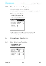
The following picture appears on the LCD display.
1) Forward power display (analog and digital)
2) Reflected power display (analog and digital)
3) General transmitter status display
4) Stylized display of exciters, amplifiers, and antenna circuit
The three boxes in the status display are allocated as follows:
W
in the box on the left - a warning exists.
F
in the box in the middle - a fault exists.
RF
in the box on the right - the transmitter output power is OK.
Transmitter set to
Local
or
Remote
mode
The three boxes in the exciter diagram are allocated as follows:
When a warning exists,
W
is displayed in the box on the left.
When a fault exists,
F
is displayed in the box in the middle.
When control power is available,
RF
is displayed in the box on the right.
The three boxes in the amplifier diagram (output stage) are allocated as follows:
When a warning exists,
W
is displayed in the box on the left.
When a fault exists,
F
is displayed in the box in the middle.
When output power is available,
RF
is displayed in the box on the right.
Содержание SR8000 Series
Страница 3: ......
Страница 7: ...5300 9677 72 0 4 EN 4 ...
Страница 8: ...Broadcasting Division 5300 9677 72 1 1 EN 4 Printed in Germany CHAPTER 1 SAFETY ...
Страница 9: ......
Страница 21: ...5300 9677 72 1 14 EN 4 Chapter1 Safety ...
Страница 22: ...Broadcasting Division 5300 9677 72 2 1 EN 4 Printed in Germany CHAPTER 2 DESIGN AND FUNCTION ...
Страница 23: ......
Страница 27: ...Chapter2 Design and Function 5300 9677 72 2 6 EN 4 Fig 4 R S SR8000 block diagram ...
Страница 49: ...Chapter2 Design and Function 5300 9677 72 2 28 EN 4 ...
Страница 50: ...Broadcasting Division 5300 9677 72 3 1 EN 4 Printed in Germany CHAPTER 3 INSTALLATION ...
Страница 51: ......
Страница 62: ...Broadcasting Division 5300 9677 72 4 1 EN 4 Printed in Germany CHAPTER 4 PUTTING INTO OPERATION ...
Страница 63: ......
Страница 88: ...Broadcasting Division 5300 9677 71 5 1 EN 4 Printed in Germany CHAPTER 5 OPERATION ...
Страница 89: ......
Страница 110: ...Chapter5 Operation 5300 9677 71 5 23 EN 4 4 Return to the previous browser window by clicking Show user list ...
Страница 157: ...Chapter5 Operation 5300 9677 71 5 70 EN 4 ...
Страница 158: ...Broadcasting Division 5300 9677 72 6 1 EN 4 Printed in Germany CHAPTER 6 MAINTENANCE ...
Страница 159: ......
Страница 165: ...Chapter6 Maintenance 5300 9677 72 6 8 EN 4 Note The software version number can also be found on the browser login page ...
Страница 166: ...Broadcasting Division 5300 9677 72 7 1 EN 4 Printed in Germany CHAPTER 7 TROUBLESHOOTING ...
Страница 167: ......
Страница 168: ...Chapter7 Troubleshooting 5300 9677 72 7 3 EN 4 CONTENTS 1 Information 4 ...
Страница 169: ...Chapter7 Troubleshooting 5300 9677 72 7 4 EN 4 1 Information The Troubleshooting chapter will be compiled later ...
Страница 170: ...Broadcasting Division 5300 9677 72 8 1 EN 4 Printed in Germany CHAPTER 8 SERVICE ...
Страница 171: ......
Страница 184: ...Broadcasting Division 5300 9677 72 9 1 EN 4 Printed in Germany CHAPTER 9 APPENDIX ...
Страница 185: ......
Страница 196: ...Chapter9 Appendix 5300 9677 72 9 13 EN 4 X32 4 Unused Signal name Direction Value range Contact Remarks ...
Страница 197: ...Chapter9 Appendix 5300 9677 72 9 14 EN 4 ...
Страница 198: ...Broadcasting Division 5300 9677 72 A 1 EN 4 Printed in Germany WIRING DIAGRAMS ...
Страница 199: ......


