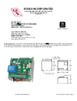


FC-40
Plus
Series
Application Note
For Circuit Board P/N’s 24-210 & 24-211
General Description
The FC-40
Plus
Series of controls are designed to
power vibratory bowls, storage hoppers and linear
inline feeders. The controls are designed to run
continuously or can be turned on and off with a PLC,
a contact closure or interlocked to the operation of a
part sensing Feeder Cube®.
Standard features include a soft start adjustment,
minimum and maximum output adjustments, full
wave/half wave selector switch, line voltage
compensation, 4-20mA and 0-5VDC amplitude
control.
Note: FC-200 Series and FC-90
Plus
Series are
available for use on applications requiring a three
wire DC sensor, an interlock output, or a Constant
Feed Rate (vibration feedback) sensor.
© 2000, 2017 RODIX
INC
.
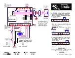
1. SELECT THE PULSE SETTING
Match the control’s pulse mode to the feeder’s
tuning:
A. For 60 pulse output - Set DIP switch (S1) to 60
on the circuit card.
B. For 120 pulse output - Set DIP switch (S1) to
120 on the circuit card.
C. For 40, 30 or 60 Reverse pulse settings, see the
“S1 Programming Chart” and the FC-40
Plus
Advanced Application Note
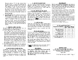
Note: Readjust the MAX trimpot after changing
pulse switch setting.
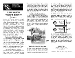
2. LIMITING THE MAXIMUM
OUTPUT OF CONTROL
The
MAX
output trimpot can be adjusted to limit the
maximum vibration level of the vibratory feeder when
the Main Control Dial is fully turned up. When setting
up the MAX output of the feeder control, the output
wiring to feeder must be connected and the control
set for the proper pulse (60 or 120) setting. A Run
Jumper must be connected as shown on either the
wiring diagram or the ON/OFF Control Guide.
A. Power input should be
OFF
or disconnected.
B. Open cover to allow access to circuit card.
C. Adjust the
MAX
Output trimpot counter-
clockwise to its minimum setting.
D. Using
CAUTION
, turn power
ON
(no output
should be present).
E. Rotate the
MAIN CONTROL DIAL
on front
cover clockwise to its highest setting.
F. Adjust the
MAX
Output trimpot so that the output
to the feeder reaches its desired maximum level.
3. SETTING THE MINIMUM
OUTPUT LEVEL OF CONTROL
When the vibratory feeder is nearly empty, turn the
MAIN CONTROL DIAL
to “1” and adjust the
MIN
trimpot to just below the proper feed rate. The MIN
trimpot also serves as the “low speed” trimpot for 2-
speed operation. See “S1 Programming Chart” for
feature selection details.
4. MAIN CONTROL DIAL
The output power is controlled by the
MAIN
CONTROL DIAL
. It is a logarithmic-tapered power
out curve (non-linear) that spreads the power
broadly across the
MAIN CONTROL DIAL
. The
logarithmic taper power curve helps to give
maximum "Fine Control" over the output speed of
the vibratory feeder. When very precise adjustment
of the
MAIN CONTROL DIAL
is needed, increase
the MIN trimpot setting and/or decrease the MAX
trimpot setting. For precise scaling at low
amplitudes, use the linear POT taper or reduce the
Max pot setting. To select a linear pot taper for the
Main Control Dial, see the “S1 Programming Chart.”
5. SETTING THE SOFT-START
The start-up rate of the control output can be
adjusted to ramp up to the desired output level
instead of starting abruptly. Soft-start keeps parts
from falling off the tooling, reduces spring shock, and
hammering when the control turns ON. Turn the
SOFT
Start trimpot clockwise for the gentlest start
(about a 6 sec. ramp up to full output). Turn the
trimpot fully counter-clockwise for no soft start.
6. REMOTE OFF/ON CONTROL
A Run Jumper has been installed at the factory as
shown on the enclosed wiring diagram.
Remote OFF/ON operation of the FC-40
Plus
Series
Feeder Cube
®
control can be configured to
operate in one of the following ways.
A. A
low current switch
such as a paddle switch
can replace the factory-installed Run Jumper
"J1." The "Run Contact" connects to terminals 6
and 7. The contact must be able to switch 5VDC
and 2mA. The control will run only when the
contact is closed. Refer to Section A of the
OFF/ON CONTROL GUIDE.
B.
Feeder Bowl/Hopper Interlock
allows the
Hopper control to operate only when the Bowl is
running and the paddle switch contact is closed.
The
interlock input
on terminals 11 and 12 of
TB2 is controlled by the
interlock output
of a
"Parts Sensing Feeder Bowl Control" such as an
FC-90
Plus
.
FC-40 Plus Set Up.doc 3/7/2018 Page 3
ADJUSTMENTS & SET UP
RODIX INC.
FEEDER CUBE
FC-90
Plus Series
GENERAL PURPOSE
RODIX INC.
FEEDER CUBE
FC-40
Plus Series


