


RODIX, INC.
Toll Free (800) 562-1868, FAX (815) 316-4701
Email [email protected]
rodix.com
VF-9 cover.docx 3/9/20 Page 2
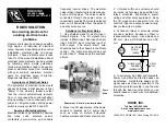
RODIX INC.
FEEDER CUBE
VF Series
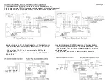
WIRING DIAGRAM
Figure 1
RODIX, INC.
Toll Free (800) 562-1868, FAX (815) 316-4701
Email [email protected]
rodix.com
VF-9 cover.docx 3/9/20 Page 2
RODIX INC.
FEEDER CUBE
VF Series
WIRING DIAGRAM
Figure 1


