


7-6
SP500 AC Drive Installation and Operation Manual Version 3.1
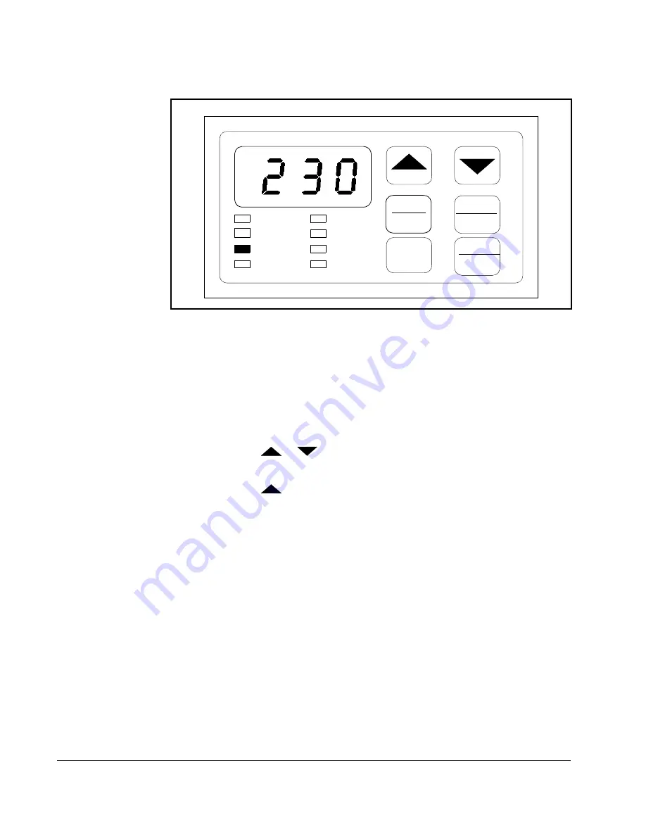
A sample monitor mode display is shown in figure 7.4.
7.5.1 Displaying the Percent Selected Speed Reference
To display the percent selected speed reference, parameter F-13 must be set to ON.
Use the following procedure to display the percent selected speed reference:
Step 1. Stop the drive (if it is running) by pressing the STOP/RESET key.
Step 2. Enter program mode by pressing the MODE/ENTER key until the PROGRAM
LED turns on.
Step 3. Press the
or
key until F-13 is displayed.
Step 4. Press the MODE/ENTER key to access the parameter.
Step 5. Press the
key until ON is displayed.
Step 6. Press the MODE/ENTER key to save the value. (F-13 will be displayed.)
Step 7. Press the STOP/REST key to exit program mode.
Step 8. Start the drive by pressing the START key.
Step 9. Press the MODE/ENTER key until all three monitor mode LEDs are on.
The display will show the active speed reference as 1 to 100% of maximum speed
(F-04).
7.5.2 Scaling the RPM Display and Reference Using F-08
The RPM display and reference can be scaled to an engineering unit to match your
application. Refer to the F-08 description in chapter 8 for this procedure.
7.6
Drive Control
When the control source is the local keypad (F-00 = 0), the keypad is used to control
the drive. This means that the drive will respond to START, STOP/RESET, and
FORWARD/REVERSE commands only from the keypad.
Figure 7.4 – Example of a Monitor Mode Display
Mode
Enter
START
Forward
Reverse
STOP
RESET
RPM
%Load
Volts
Remote
RUN
Program
Forward
Reverse
Содержание Reliance SP500
Страница 1: ...Instruction Manual SP500 AC Drive Installation and Operation Manual Version 3 1 D2 3356 5 ...
Страница 6: ...IV SP500 AC Drive Installation and Operation Manual Version 3 1 ...
Страница 8: ...VI SP500 AC Drive Installation and Operation Manual Version 3 1 ...
Страница 10: ...1 2 SP500 AC Drive Installation and Operation Manual Version 3 1 ...
Страница 13: ...Learning About the SP500 Drive 2 3 Figure 2 1 SP500 System Diagram ...
Страница 14: ...2 4 SP500 AC Drive Installation and Operation Manual Version 3 1 Figure 2 2 SP500 System Diagram Continued ...
Страница 15: ...Learning About the SP500 Drive 2 5 Figure 2 3 Regulator Board Component Locations ...
Страница 22: ...2 12 SP500 AC Drive Installation and Operation Manual Version 3 1 Figure 2 8 Enclosure D Component Locations ...
Страница 24: ...2 14 SP500 AC Drive Installation and Operation Manual Version 3 1 ...
Страница 27: ...SP500 System Planning 3 3 Figure 3 3 Enclosure C Dimensions Figure 3 4 Enclosure D Dimensions ...
Страница 36: ...4 2 SP500 AC Drive Installation and Operation Manual Version 3 1 Figure 4 1 Enclosure A Wire Routing Locations ...
Страница 37: ...Installing the Drive 4 3 Figure 4 2 Enclosure B Wire Routing Locations ...
Страница 38: ...4 4 SP500 AC Drive Installation and Operation Manual Version 3 1 Figure 4 3 Enclosure C Wire Routing Locations ...
Страница 39: ...Installing the Drive 4 5 Figure 4 4 Enclosure D Wire Routing Locations ...
Страница 44: ...4 10 SP500 AC Drive Installation and Operation Manual Version 3 1 ...
Страница 56: ...5 12 SP500 AC Drive Installation and Operation Manual Version 3 1 ...
Страница 60: ...6 4 SP500 AC Drive Installation and Operation Manual Version 3 1 ...
Страница 68: ...7 8 SP500 AC Drive Installation and Operation Manual Version 3 1 ...
Страница 86: ...8 18 SP500 AC Drive Installation and Operation Manual Version 3 1 ...
Страница 110: ...E 8 SP500 AC Drive Installation and Operation Manual Version 3 1 ...
Страница 118: ...Index 4 SP500 AC Drive Installation and Operation Manual Version 3 1 ...
Страница 120: ......
Страница 121: ......
Страница 122: ...Publication D2 3356 5 July 1999 1999 Rockwell International Corporation All rights reserved Printed in USA ...


