


3-50
Programming and Parameters
PowerFlex 700S Phase II AC Drive User Manual -
Publication 20D-UM006G-EN-P – July 2008
329
Fault TP Sel
Enter or write a value to select Fault data displayed in
•
24 “ElpsSec.mSec” = Elapsed time in seconds and milliseconds since the last power up
•
25 “ElpsMin.Sec” = Elapsed time in minutes and seconds since the last power up
•
26 “ElpsHour.Min” = Elapsed time in hours and minutes since the last power up
•
27 “ElpsDay.Hour” = Elapsed time in days and hours since the last power up
Note: 'Values 24 - 27 were added for firmware version 4.002.
Default:
Options:
0 =
0 =
1 =
2 =
3 =
4 =
5 =
6 =
7 =
8 =
9 =
10 =
11 =
12 =
13 =
“Zero”
“Zero”
14 = “MtrStallTime”
“Abs OverSpd”
15 = “MC Handshake”
“EE Pwr State”
16 = “VPL Handshak”
“Inv DataStat”
17 = “MC Diag”
“Run Time Err”
18 = “PwrLossState”
“LowBus Thres”
19 = “12 volt loss”
“LowBus Detct”
20 = “PwrEE Chksum”
“PwrLosBusVlt”
21 = “Db Read Cnt1”
“MCPLosBusVlt”
22 = “Db Read Cnt2”
“MC Flt Reset”
23 = “Db Read Cnt3”
“Ext Flt Stat”
24 = “ElpsSec.mSec”
“VPL TaskErr”
25 = “Elps Min.Sec”
“Mtr OL Input”
26 = “ElpsHour.Min”
“Mtr OL Outpt”
27 = “ElpsDay.Hour”
330
Fault TP Data
[Fault TP Sel].
Default:
Min/Max:
0
-/+2200000000
RO Real
331 LstFaultStopMode
Displays the action taken by the drive during the last fault. When a fault occurs, an action is
taken as a result of that fault.
Default:
Options:
0 =
0 =
1 =
2 =
“Ignore”
“Ignore”
3 = “Flt RampStop“
“Alarm”
4 = “FltCurLimStop”
“FltCoastStop”
332
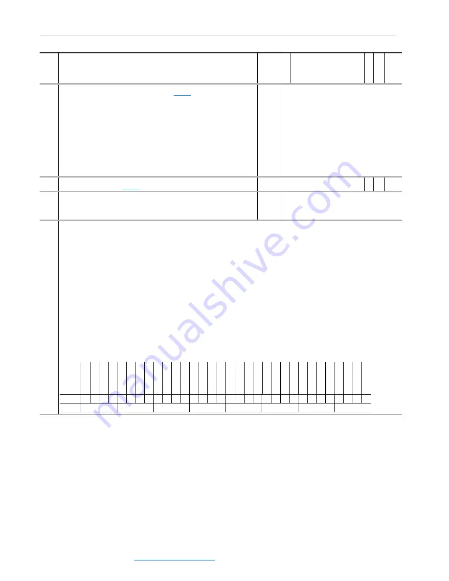
700L EventStatus
Indicates the presence of certain drive anomalies for PowerFlex 700L (LiquiFlo) drive.
Bit 0 “Dsat Phs U1” indicates that the primary structure detected a Dsat on phase U.
Bit 1 “Dsat Phs V1” indicates that the primary structure detected a Dsat on phase V.
Bit 2 “Dsat Phs W” indicates that the primary structure detected a Dsat on phase W.
Bit 3 “Ovr Current1” indicates that the primary structure detected an over current.
Bit 4 “Ovr Volt1” indicates that the primary structure detected an over voltage.
Bit 5 “Asym DcLink1” indicates that the primary structure detected an unbalanced DC Link.
Bit 6 “Pwr Suply1” indicates that the primary structure detected a power supply failure.
Bit 7 “HW Disable1” indicates that the primary structure detected a hardware disable.
Bit 8 “Latch Err1” indicates that the primary structure fault was generated but no indicating bit was set.
Bit 14 “Cnv NotLogin” the converter was expected but none logged in.
Bit 15 “Cnv NotStart” the converter was commanded to start but did not become active.
Bit 16 “Dsat Phs U2” the second structure detected a Dsat on phase U.
Bit 17 “Dsat Phs V2” the second structure detected a Dsat on phase V.
Bit 18 “Dsat Phs W2” the second structure detected a Dsat on phase W.
Bit 19 “Ovr Current2” the second structure detected an over current.
Bit 20 “Ovr Volt2” the second structure detected an over voltage.
Bit 21 “Asym DcLink2” the second structure detected an unbalanced DC Link.
Bit 22 “Pwr Suply2” the second structure detected a power supply failure.
Bit 23 “HW Disable2” the second structure detected a hardware disable.
Bit 24 “Latch Err2” the second structure fault was generated but no indicating bit was set.
Note: This parameter was added for firmware version 2.03.
No.
Name
Description
Values
Linkab
le
R
ead-Wr
ite
Da
ta
T
ype
Options
Rese
rv
ed
Rese
rv
ed
Rese
rv
ed
Rese
rv
ed
Rese
rv
ed
Rese
rv
ed
Rese
rv
ed
Lat
ch Er
r2
HW Dis
ab
le2
Pwr Su
ply2
Asy
m
Dc
Link2
Ovr V
olt2
Ovr
Cu
rr
ent
2
Dsat Phs W2
Dsat Phs V2
Dsat Phs U2
Cn
v NotStar
t
Cn
v NotLog
in
Rese
rv
ed
Rese
rv
ed
Rese
rv
ed
Rese
rv
ed
Rese
rv
ed
Lat
ch Er
r1
HW Dis
ab
le1
Pwr Su
ply1
Asy
m
Dc
Link1
Ovr V
olt1
Ovr
Cu
rr
ent
1
Dsat Phs W1
Dsat Phs V1
Dsat Phs U1
Default
0
0
0
0
0
0
0
0
0
0
0
0
0
0
0
0
0
0
0
0
0
0
0
0
0
0
0
0
0
0
0
0
Bit
31 30 29 28 27 26 25 24 23 22 21 20 19 18 17 16 15 14 13 12 11 10 9
8
7
6
5
4
3
2
1
0
0 = False
1 = True
Содержание PowerFlex 700S
Страница 1: ...USER MANUAL Firmware Versions 1 xxx 4 002 PowerFlex 700S High Performance AC Drive Phase II Control ...
Страница 58: ...2 8 Start Up PowerFlex 700S Phase II AC Drive User Manual Publication 20D UM006G EN P July 2008 Notes ...
Страница 147: ...Programming and Parameters 3 89 PowerFlex 700S Phase II AC Drive User Manual Publication 20D UM006G EN P July 2008 ...
Страница 278: ...D 8 HIM Overview PowerFlex 700S Phase II AC Drive User Manual Publication 20D UM006G EN P July 2008 Notes ...
Страница 316: ...Index 6 PowerFlex 700S Phase II AC Drive User Manual Publication 20D UM006G EN P July 2008 ...
Страница 317: ......