


234
Rockwell Automation Publication 520-UM001K-EN-E - August 2021
Appendix F PID Set Up
parameter is scaled so that when it is set to 1.00, the process response is
0.1% of
[Maximum Freq] when the process error is changing at 1% /
second. A larger value for [PID x Diff Rate] makes the differential term
have more of an effect and a small value makes it have less of an effect.
In many applications, the D gain is not needed. Setting [PID x Diff Rate]
to 0.00 (factory default) disables the differential component of the PID
loop.
Guidelines for Adjusting the PID Gains
1. Adjust the proportional gain. During this step it may be desirable to
disable the integral gain and differential gain by setting them to 0. After
a step change in the PID Feedback:
- If the response is too slow increase A461 or A473 [PID x Prop Gain].
- If the response is too quick and/or unstable (see
), decrease A461 or A473 [PID x Prop Gain].
- Typically, A461 or A473 [PID x Prop Gain] is set to some value below the
point where the PID begins to go unstable.
2. Adjust the integral gain (leave the proportional gain set as in Step 1).
After a step change in the PID Feedback:
- If the response is too slow (see
Slow Response – Over Damped on
), or the PID Feedback does not become equal to the PID
Reference, decrease A462 or A474 [PID x Integ Time].
- If there is a lot of oscillation in the PID Feedback before settling out
(see
Oscillation – Under Damped on page 235
), increase A462 or A474
[PID x Integ Time].
3. At this point, the differential gain may not be needed. However, if after
determining the values for A461 or A473 [PID x Prop Gain] and A462 or
A474 [PID x Integ Time]:
- Response is still slow after a step change, increase A463 or A475 [PID x
Diff Rate].
- Response is still unstable, decrease A463 or A475 [PID x Diff Rate].
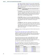
The following figures show some typical responses of the PID loop at different
points during adjustment of the PID Gains.
Unstable Response
Slow Response – Over Damped
PID Feedback
PID Reference
Time
PID Feedback
PID Reference
Time
Содержание Allen-Bradley PowerFlex 520 Series
Страница 8: ...8 Rockwell Automation Publication 520 UM001K EN E August 2021 Table of Contents Notes ...
Страница 68: ...68 Rockwell Automation Publication 520 UM001K EN E August 2021 Chapter 2 Start Up Notes ...
Страница 156: ...156 Rockwell Automation Publication 520 UM001K EN E August 2021 Chapter 3 Programming and Parameters Notes ...
Страница 202: ...202 Rockwell Automation Publication 520 UM001K EN E August 2021 Appendix B Accessories and Dimensions Notes ...
Страница 236: ...236 Rockwell Automation Publication 520 UM001K EN E August 2021 Appendix F PID Set Up Notes ...
Страница 262: ...262 Rockwell Automation Publication 520 UM001K EN E August 2021 Appendix J PowerFlex 525 PM Motor Configuration Notes ...
Страница 270: ...270 Rockwell Automation Publication 520 UM001K EN E August 2021 Index Notes ...