


2
Sensor Selection
Output Characteristics
Catalog Number
Operating
Voltage
Current
Consumption
Type
Max Load
Current
Max Leakage
Current
Response
Time
LED
Cable
Pico
Power Bus
(QD required)
Red
45FVL-2LHE-A2
45FVL-2LHE-P4
45FVL-2LHE-C4
Ê
50ma or Less
PNP
Green
45FVL-3LHE-A2
45FVL-3LHE-P4
45FVL-3LHE-C4
Ê
50ma or Less
PNP
Blue
45FVL-6LHE-A2
45FVL-6LHE-P4
45FVL-6LHE-C4
Ê
12-24V DC
Output: 100ma
0 5ma
600
µ
s
White
45FVL-5LHE-A2
45FVL-5LHE-P4
45FVL-5LHE-C4
Ê
C
+/- 10%
Output: 100ma
Stability: 50ma
0.5ma
600
µ
s
Red
45FVL-2LGE-A2
45FVL-2LGE-P4
45FVL-2LGE-C4
Ê
+/ 10%
39ma or Less
NPN
Green
45FVL-3LGE-A2
45FVL-3LGE-P4
45FVL-3LGE-C4
Ê
39ma or Less
NPN
Blue
45FVL-6LGE-A2
45FVL-6LGE-P4
45FVL-6LGE-C4
Ê
White
45FVL-5LGE-A2
45FVL-5LGE-P4
45FVL-5LGE-C4
Ê
Ê
PowerBus master/3 conductor QD = 45F–A3C–A2. PowerBus slave/1 conductor QD = 45F–A1C–A2
Output and Stability Indicators
Two LEDs (green and orange) indicate a variety of conditions
to facilitate set-up and troubleshooting. The function of each is
described in the table below. Relevant output and stability
data are also shown.
LED
State
Condition
Green
OFF
ON
Unstable light signal
Stable light signal
Orange
OFF
ON
Output OFF
Output ON
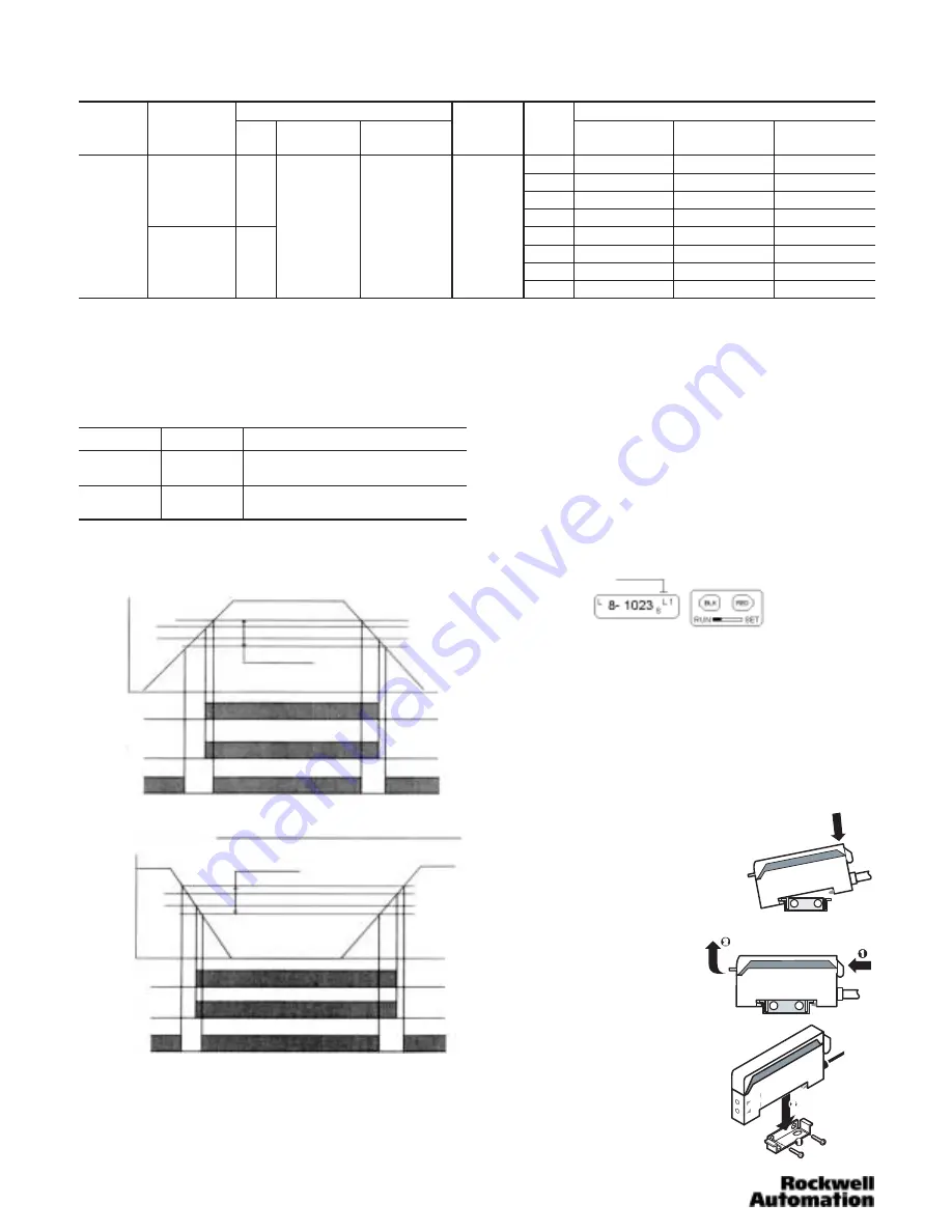
Operation Indicator and Stability Indicator
Light on operation
Stable range level
On level
Off level
Unstable range level
Unstable range
Operation
Indicator
Output
Light level
Stability
Indicator
On
On
On
On
On
Unstable range
Stable range
(light interrupted)
Stable range
(light interrupted)
Stable range
(light on)
Unstable range
Dark on operation
Stable range level
Off level
On level
Unstable range level
Unstable range
Operation
Indicator
Output
Stability
Indicator
On
On
On
On
On
Unstable range
Stable range
(light interrupted)
Stable range
(light interrupted)
Stable range
(light on)
Unstable range
Light level
Operation Selector Switch
When the selector switch is in the RUN position (see following
example), the sensor will function normally, and all settings
are locked from adjustment. The SET position unlocks the
sensor’s settings, allowing the user to either adjust the sensor
manually, or use the self-teach functionality. When
adjustments are complete, return the switch to the RUN
position (settings become locked). If a manual sensitivity
adjustment is required a user can unlock this setting by
(quickly) switching from RUN to SET to RUN. The sensor will
display a flashing “S” on the LCD display, and the user can
now adjust the sensitivity setting. The sensor will automatically
return to the locked condition 10 seconds after sensitivity
adjustment is complete.
Locking
Two Adjustment Buttons
The red button is used to teach the sensor, change the
frequency and to increase the sensitivity.
The black button is used to change the operating mode,
indication mode and to decrease sensitivity.
Both buttons are inactive in the RUN mode.
Mounting the Sensor
How to Attach Sensor to DIN Rail
Attach front hook of the photoelectric
sensor onto rail (or Mounting bracket)
and press rear end of sensor down
until unit snaps into place.
How to Detach Sensor from DIN Rail
Pushing the sensor unit forward,
pull up on the front of the sensor
until the front hook is detached.
Remove sensor.
Side Mounting Sensor with Bracket
Fasten mounting bracket assembly
using M3 screws. Tightening torque is
0.8Nm max. Attach front hook of the
photoelectric sensor onto mounting
bracket and press rear end of sensor
down until unit snaps into place.